
Apparatus and method for monitoring resistance spot welding quality

A technology of resistance spot welding and quality monitoring, applied in the direction of measuring devices, resistance welding equipment, welding equipment, etc., can solve the problems of signal distortion, lack of better practical methods, and failure to obtain universal characteristic information of resistance spot welding quality. To achieve the effect of improving the signal-to-noise ratio

Inactive Publication Date: 2008-06-18
TIANJIN UNIVERSITY OF SCIENCE AND TECHNOLOGY
View PDF0 Cites 43 Cited by
  • Summary
  • Abstract
  • Description
  • Claims
  • Application Information

AI Technical Summary

Problems solved by technology

However, this literature does not obtain universal characteristic information that can reflect the quality of resistance spot welding
[0006] (2) Constant heat or constant energy control method, which measures the electrode voltage and electrode current of resistance spot welding at the same time. Due to the high current of resistance spot welding, the electromagnetic induction noise is very large, although it can be realized by reducing the area covered by the twisted pair Noise reduction method, however, due to the limitations of the conditions of use in industrial applications, the area of ​​the twisted pair envelope cannot be reduced to a small size, resulting in serious signal distortion
As for how to use fewer sensors to obtain feature information that has a clear correspondence with spot welding quality to achieve spot welding quality monitoring, there is no good practical method in the prior art. At the same time, the stability and quality of resistance spot welding quality monitoring The scope of application cannot meet the practical requirements

Method used


Image

  • Apparatus and method for monitoring resistance spot welding quality
  • Apparatus and method for monitoring resistance spot welding quality
  • Apparatus and method for monitoring resistance spot welding quality

Examples


Embodiment Construction

[0037] Embodiments of the present invention are described in further detail below in conjunction with the accompanying drawings:

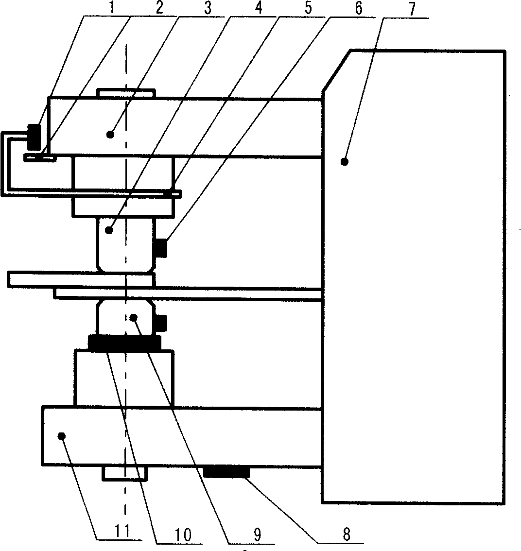
[0038] The following takes the DJ-1000 DC spot welding machine as the main body of the resistance welding equipment as an example. The resistance spot welding quality monitoring device consists of the main body 7 of the resistance spot welding equipment, the upper arm 3, the lower arm 11, the upper electrode The electrode 9 is composed of a displacement sensor 1 installed above the rigid bracket 5 fixed on the upper electrode. The lower surface of the displacement sensor is parallel to the metal plate 2 extending horizontally from the outside of the upper machine arm. The displacement sensor realizes synchronous movement with the upper electrode. The change of the relative position with the metal plate reflects the change of the distance between the two; the two electrodes of the voltage sensor 6 are respectively installed on the upper electrode and...


PUM

PropertyMeasurementUnit
Number of turnsaaaaaaaaaa

Abstract

The invention belongs to a resistance spot welding quality monitoring device and a monitoring method in the field of metallic material resistance spot welding. The invention is characterized in that an independent displacement transducer, an independent electric pressure transducer, an independent current sensing device, an independent pressure transducer are arranged at different positions of a spot-welding equipment; the sensors are connected with a data acquisition analytic device. As the device adopts the method of diagnostic information extraction and the information integration during the course of spot welding, the quality of resistance spot welding can be monitored and determined on line; and the diagnostic information during the course of spot welding can be analyzed effectively. In addition, the diagnostic information abstracted has high signal to noise ratio, and distinct characteristics; and is stable. The resistance spot welding quality monitoring specimens abstracted have the advantages of expandability and so on, and can be widely used. The device is properly designed, and can be installed and maintained conveniently. Accordingly, the invention is highly practical; the implementation cost is low; and the invention can be promoted and applied easily.

Description

technical field [0001] The invention belongs to the field of resistance spot welding of metal materials, in particular to a resistance spot welding quality monitoring device and a monitoring method composed of multiple sensors and a data acquisition device. Background technique [0002] The resistance spot welding process is a highly nonlinear process with a large number of uncertain factors interacting with each other. Since the nucleation of resistance spot welding is in a closed state and cannot be directly observed, and the nucleation time is extremely short, short-term fluctuations in welding conditions will cause serious defects such as spattering, incomplete fusion or incomplete fusion. This is especially true for resistance spot welding of aluminum alloys. In actual production, due to the influence of many factors such as the change of the surface state of the workpiece, electrode wear, assembly clearance and disturbance of the mechanical structure, even if the prod...

Claims


Application Information

Patent Timeline
IPC IPC(8): G01N33/00G05B19/048B23K11/11
Inventor 潘存海
Owner TIANJIN UNIVERSITY OF SCIENCE AND TECHNOLOGY
Features
  • Generate Ideas
  • Intellectual Property
  • Life Sciences
  • Materials
  • Tech Scout
  • Unparalleled Data Quality
  • Higher Quality Content
  • 60% Fewer Hallucinations
Learn More