

Commingle discharging shadow mask type plasma display panel and driving method thereof
A plasma and display panel technology, which is applied to static indicators, solid cathode parts, instruments, etc., can solve the problems of low yield and high production cost of plasma display panel barriers, and achieve low cost, high luminous efficiency, and high production efficiency. The effect of simple process
- Summary
- Abstract
- Description
- Claims
- Application Information
AI Technical Summary
Problems solved by technology
Method used
Image

Examples
Embodiment 1
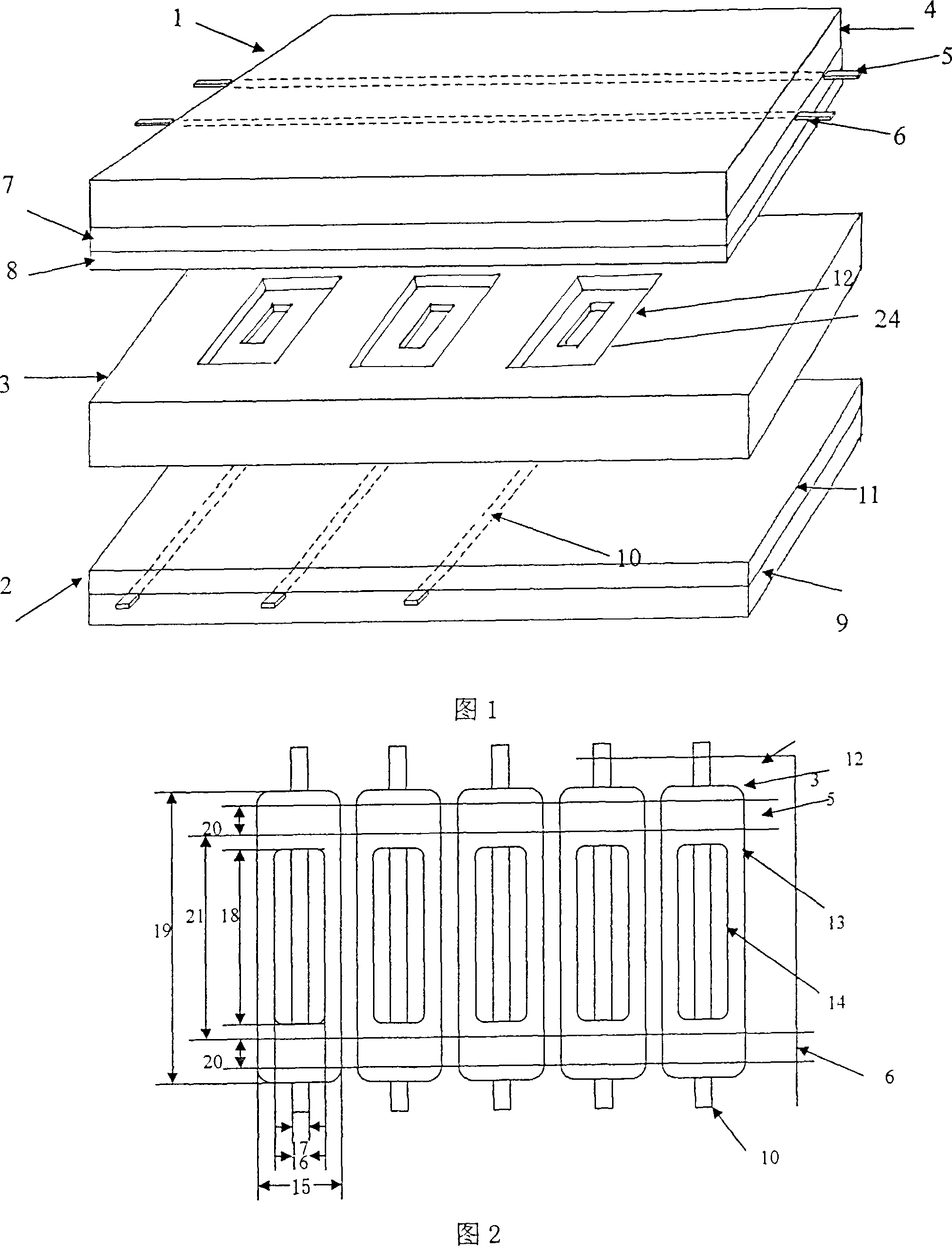
[0025] As shown in Figures 1~3, 5
[0026]A mixed discharge shadow mask type plasma display panel, as shown in FIG. The front substrate 1 is mainly composed of a front substrate glass substrate 4, first electrode pairs 5, 6, a dielectric layer 7, and a protective film 8, wherein the first electrode pairs 5, 6 are arranged in parallel and located on the front substrate glass substrate 4 Above, the electrode composed of Al or Ag electrode + transparent conductive film (ITO), the electrode 5 is called the sustain electrode, the electrode 6 is called the scan electrode, the dielectric layer 7 covers the first electrode pair 5, 6, and the protective film 8 is covered on the dielectric layer 7. The rear substrate 2 is mainly composed of a rear substrate glass substrate 9, a second electrode 10, and a dielectric layer 11, wherein the second electrode 10 is located on the rear substrate glass substrate 9, and the dielectric layer 11 covers the second electrode 10. The second electro...
Embodiment 2
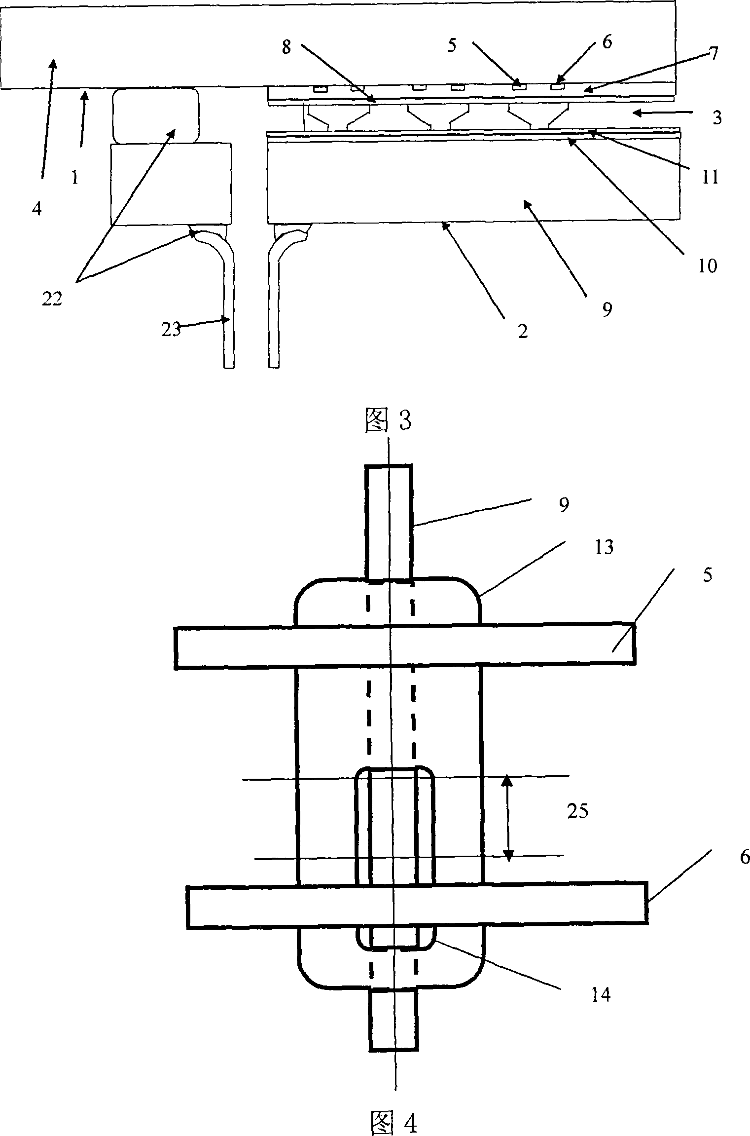
[0031] As shown in Figure 4.
[0032] In the first embodiment above, when the center of the lower opening 14 and the center of the upper opening 13 of the grid hole 12 of the shadow mask are arranged eccentrically along the direction of the electrode 10, the upper and lower openings are projected on the same plane parallel to the surface of the shadow mask Above, the center eccentric distance 25 is 0.1-0.4 times of the length 19 of the upper opening. In the discharge cell, the sustain electrode 6 in the first electrode pair deviates from the lower opening length 18 of 0.1 to 0.4 times the upper opening center of the grid hole 12, corresponding to the lower opening center, so that the first electrode 6 and the electrode 10 are generated between The discharge distance of the opposed discharge is shorter, and the ignition voltage is further reduced. The schematic diagram of the discharge unit is shown in Figure 4, which constitutes the second embodiment group of the present inven...
Embodiment 3
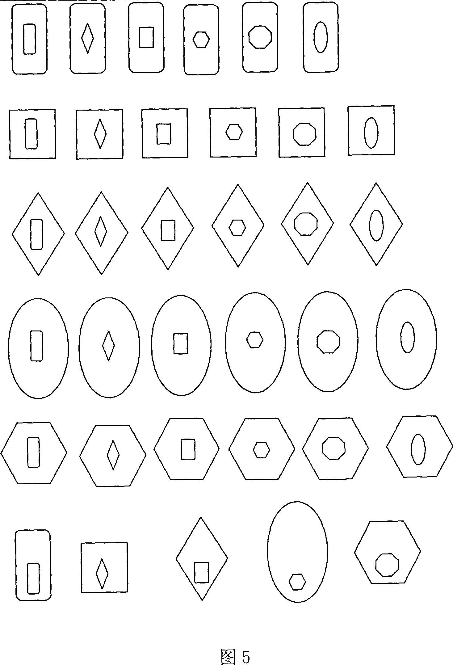
[0034] In the above-mentioned first embodiment, the upper opening of the shadow mask grid hole 12 is a kind of any polygonal structure such as elongated, quadrangular, circular, trapezoidal, hexagonal or octagonal, and the lower opening is elongated, quadrangular, etc. , circular, trapezoidal, hexagonal or octagonal and other arbitrary polygons, the lower opening and the upper opening can be arranged concentrically or eccentrically, and the upper and lower opening structures can be combined arbitrarily. As shown in Fig. 5, this constitutes the third embodiment group of the present invention, and the working principle is the same as that of the first embodiment.
PUM
 Abstract
Description
Claims
Application Information