Liquid crystal display having photoelectric converting function

A technology for display devices and photovoltaic cells, applied in photovoltaic power generation, identification devices, circuits, etc.

Inactive Publication Date: 2008-06-18
TPO HONG KONG HLDG
View PDF2 Cites 14 Cited by
  • Summary
  • Abstract
  • Description
  • Claims
  • Application Information

AI Technical Summary

Problems solved by technology

Moreover, the solar battery unit is arranged independently of the liquid crystal display panel (that is, the liquid crystal cell referred to in Document 2), so the entire system tends to be larger.

Method used


Image

  • Liquid crystal display having photoelectric converting function
  • Liquid crystal display having photoelectric converting function
  • Liquid crystal display having photoelectric converting function

Examples


Embodiment Construction

[0051] Hereinafter, the above-mentioned aspects and other embodiments of the present invention will be described in detail with reference to the drawings using examples.

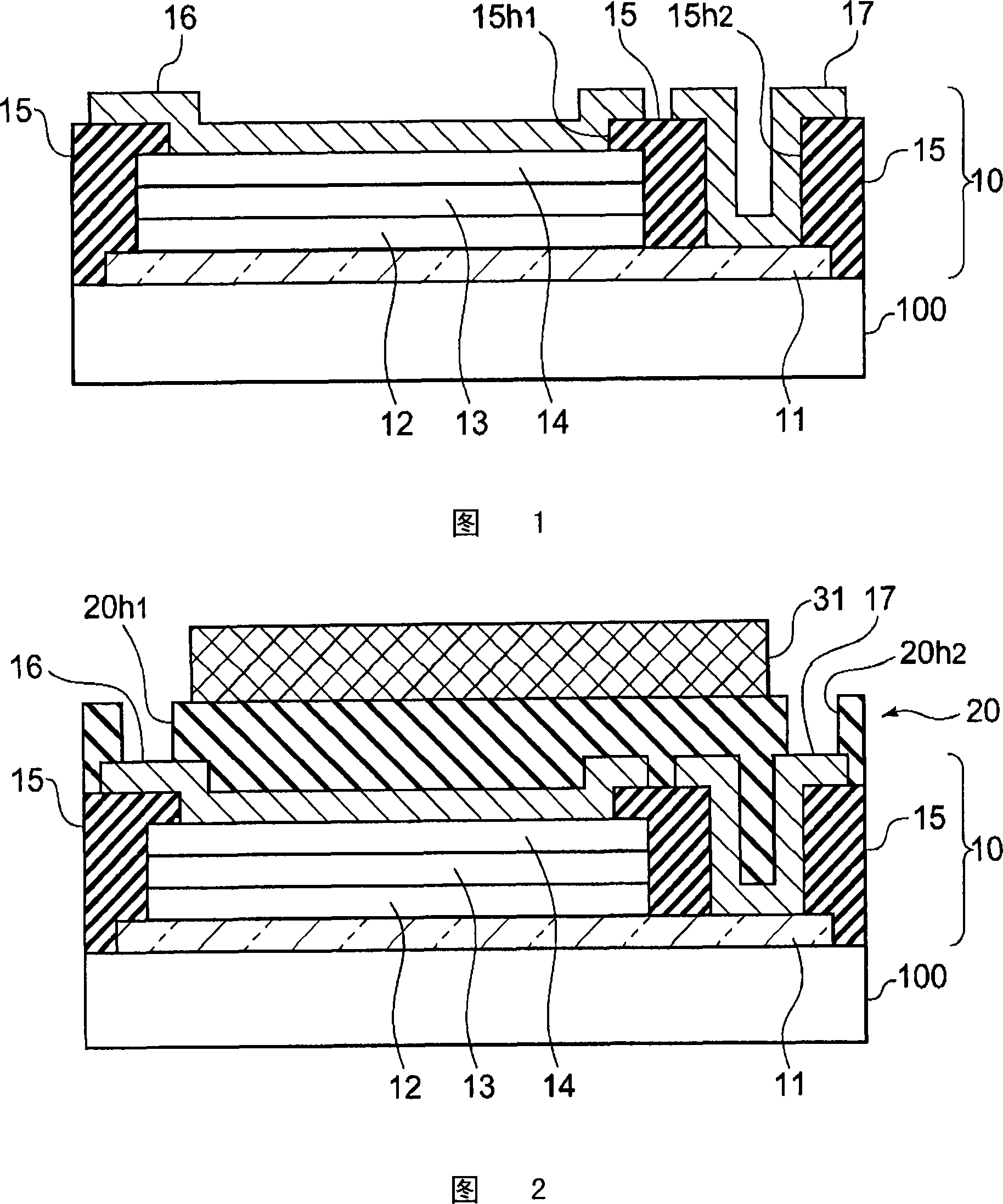
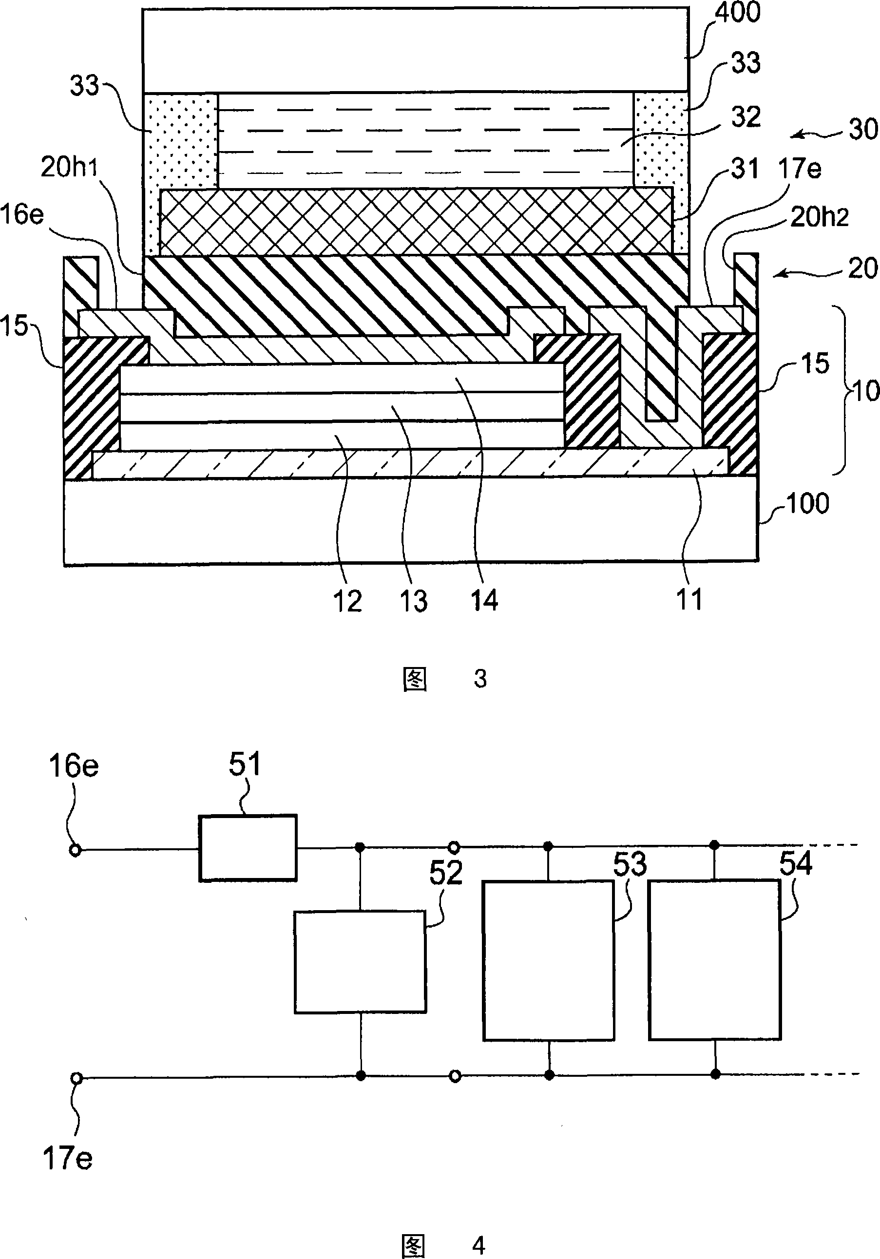
[0052] 1 to 3 are respective schematic cross-sectional structures showing main manufacturing steps of a liquid crystal display device according to an embodiment of the present invention.

[0053] In FIG. 1 , a state in which a photovoltaic cell layer is formed on a rear substrate is shown. Here, first, a rear substrate 100 made of a glass substrate or other translucent thin plate is prepared as a base layer, and a transparent conductive layer 11 made of, for example, ITO (indium tin oxide) is formed thereon. Here, the transparent conductive layer 11 is formed on substantially the entire main surface of the rear substrate 100 , but its edge is formed at a position not exceeding the end surface of the substrate 100 as shown in the figure. In this example, a so-called PIN diode structure type solar cell is emp...


PUM


Abstract

Disclosed is a photocell structure capable of photoelectrically converting the outside light efficiently in a display such as a reflective liquid crystal display. Specifically disclosed is a display comprising light-transmitting front and back substrates (400, 100) arranged opposite to each other, and an optical modulation layer (30) arranged between these substrates, in which display an image formed by the optical modulation layer (30) is displayed to the outside of the front substrate (400). This display also comprises a photocell layer (10) which is so formed between the back substrate (100) and the optical modulation layer (30) over a certain region of the major surface of the back substrate (100) as to be supported by the back substrate (100) which serves as a base layer therefor. This photocell layer (10) receives outside light coming from the outside of the back substrate (100) through the back substrate (100). The display further comprises a insulating planarization layer (20) formed on the upper surface of the photocell layer (10), and the optical modulation layer (30) is so formed as to be supported by this planarization layer (20).

Description

technical field [0001] The present invention relates to a liquid crystal display device with a photoelectric conversion function, in particular to a liquid crystal display device with a photovoltaic cell structure. Background technique [0002] Conventionally, a liquid crystal display device has been studied in which a solar cell is incorporated into a liquid crystal display device, and the power obtained from the solar cell is used to drive the liquid crystal display device and / or charge the battery. [0003] In Patent Document 1, it was disclosed that it belongs to this type, and in a reflective liquid crystal optoelectronic device in which a scattering liquid crystal layer is sandwiched between transparent substrates, a solar cell is formed on the lower substrate, and a part of it is used to form an active element, and the structure can be highly efficient. A technique to time-separately drive a scattering-type liquid crystal layer. [0004] In addition, Patent Document ...

Claims


Application Information

Patent Timeline
Patent Type & Authority Applications(China)
IPC IPC(8): G09F9/00G02F1/1333G02F1/1335G02F1/157G02F1/167G09F9/30H01L31/042H01L51/50
CPCG02F1/13306Y02E10/52H01L31/075G02F2001/13324H01L31/04Y02E10/548G02F1/13324
Inventor 田中秀夫
Owner TPO HONG KONG HLDG
Why Eureka
Try Eureka