High accuracy ball double autorotation grinding tray high-efficiency grinding device

A technology of a grinding device and a grinding disc, which is applied in the field of high-precision spherical parts processing and spherical parts grinding device, can solve the problems of low processing sphericity, poor processing consistency, low processing efficiency, etc., so as to improve grinding efficiency and reduce precision requirements. , Improve the effect of grinding precision

Inactive Publication Date: 2008-06-25
ZHEJIANG UNIV OF TECH
View PDF0 Cites 28 Cited by
  • Summary
  • Abstract
  • Description
  • Claims
  • Application Information

AI Technical Summary

Problems solved by technology

[0007] The purpose of the present invention is to overcome the problems of low processing sphericity precision, poor processing consistency, low processing efficiency and high cost in the existing spherical part grinding disc processing technology, and provide a kind of processing accuracy, processing efficiency, high processing consistency, and the equipment at the same time A grinding device with simple structure and low precision requirements for processing and assembly

Method used


Image

  • High accuracy ball double autorotation grinding tray high-efficiency grinding device
  • High accuracy ball double autorotation grinding tray high-efficiency grinding device
  • High accuracy ball double autorotation grinding tray high-efficiency grinding device

Examples


Embodiment 1

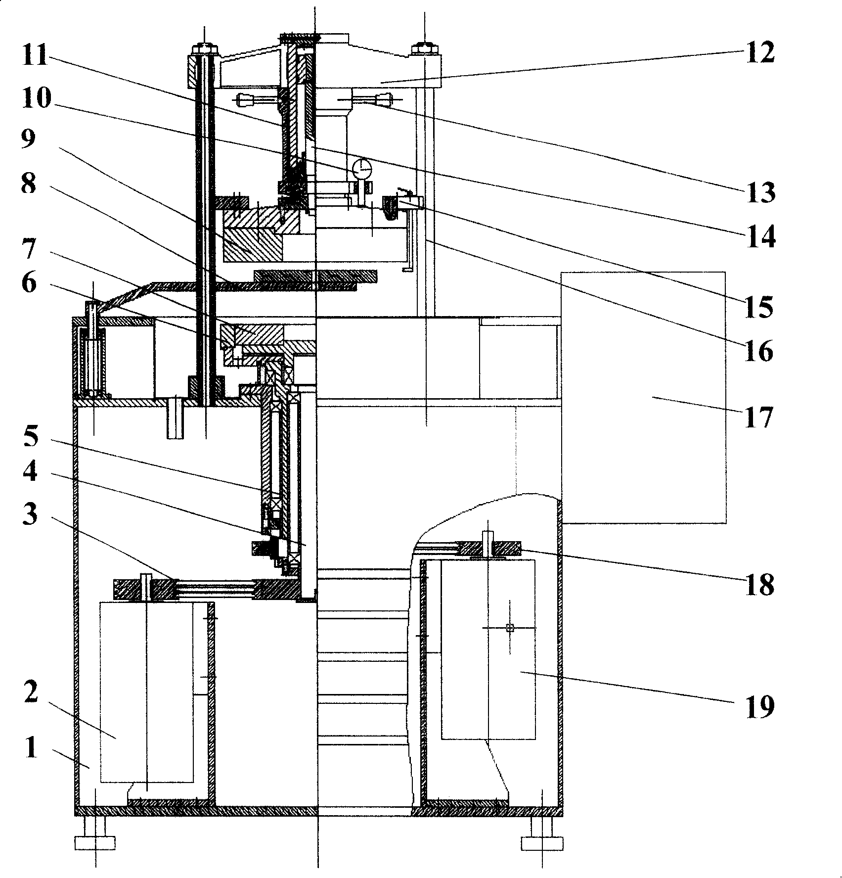
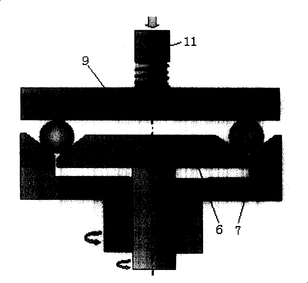
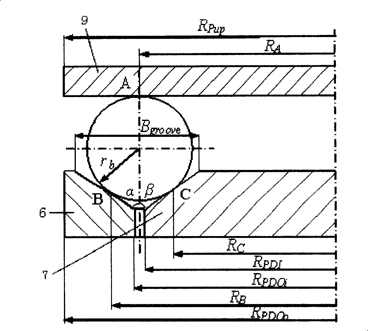
[0028] Referring to the attached drawings: The high-precision ball double-rotation grinding disc high-efficiency grinding device includes an upper grinding disc 9, a lower grinding outer disc 6, a lower grinding disc inner disc 7, a drive motor 2 for the lower grinding disc inner disc, and a lower grinding disc inner disc, which are arranged on the frame 1. Transmission device 3, lower grinding disc inner disc main shaft 4, lower grinding disc outer disc drive motor 19, lower grinding disc outer disc transmission device 18, lower grinding disc outer disc main shaft 5, tray 8, pressing device 11, dynamometer 10, beam 12, The locking mechanism 13, the pressing rod 14, the blocking arm 15, the upright column 16, the console 17, the tapered grinding surface on the outside of the inner disc of the lower grinding disc and the tapered grinding surface on the inside of the outer disc of the lower grinding disc form a V-shaped groove structure, and The upper grinding disc together const...

Embodiment 2

[0045] The drive shafts of the upper grinding disc and the inner disc of the lower grinding disc are connected with different motors, and the outer lower grinding disc is connected with the processing load device. The remaining structures and implementations of this embodiment are the same as those of the first embodiment.

Embodiment 3

[0047] The drive shafts of the upper grinding disc and the lower grinding outer disc are connected with different motors, and the inner disc of the lower grinding disc is connected with the processing load device.

[0048] The remaining structures and implementations of this embodiment are the same as those of the first embodiment.


PUM


Abstract

A high precision ball double rotation abrasive disk high efficiency grinding unit includes an upper abrasive disk, a lower abrasive disk and an inner disk of the lower abrasive disk arranged on a frame. The cone abrasive surface at the outer side of the inner disk of the lower abrasive disk and the cone abrasive surface at the inner side of an outer disk of the lower abrasive disk form a V-shaped slot structure which together with the upper abrasive disk forms three machining contact points of a grinding ceramics ball. The drive axes of any two parts in the upper abrasive disk, the outer disk of the lower abrasive disk and the inner disk of the lower abrasive disk are selected to be connected with an electric motor. The parts not connected with a drive motor machine a loading device. The invention can realize the relative orientation adjustment of a rotating axis and a revolution axis for a ball rough and realizes uniform grinding / polishing of the ball rough surface. The invention has the advantages of high machining precision, machining efficiency and machining consistency, and simultaneously the drive and transmission devices have been reduced from 3 to 2. The invention has a simple structure and is a grinding unit with less requirements for machining and assembling precisions.

Description

(1) Technical field [0001] The invention relates to a spherical part grinding device, in particular to a precision grinding / polishing processing device for high-precision ceramic balls in high-speed, high-precision ceramic ball bearings, and belongs to the high-precision spherical part processing technology. (2) Background technology [0002] High-precision balls are important components in roundness meters, gyroscopes, bearings and precision measurement, and are often used as the benchmark for precision measurement. They play a very important role in precision equipment and precision machining, especially in ball bearings. The key parts of ball bearings, the accuracy of bearing balls (spherical deviation, ball diameter variation and surface roughness) directly affect the technical indicators of ball bearings such as motion accuracy, noise and life, and then affect the performance of equipment and instruments. Compared with the traditional bearing steel ball material (GCr15)...

Claims


Application Information

Patent Timeline
Patent Type & Authority Applications(China)
IPC IPC(8): B24B11/06
Inventor 袁巨龙吕冰海王志伟许秦
Owner ZHEJIANG UNIV OF TECH
Why Eureka
Try Eureka