
Drive unit of gas discharge lamp

A technology for gas discharge lamps and driving devices, which is applied in the use of gas discharge lamps, output power conversion devices, lighting devices, etc., and can solve problems such as high starting frequency, increased power consumption of switching tubes, and large differences in voltage and current. question

Inactive Publication Date: 2008-06-25
叶建国
View PDF0 Cites 12 Cited by
  • Summary
  • Abstract
  • Description
  • Claims
  • Application Information

AI Technical Summary

Problems solved by technology

These waveforms all indicate that the switching circuit of the electronic ballast is working in a hard switching state. At this time, the power consumption of the switching tube increases, the temperature rises, the stress becomes worse, and it is very easy to damage
[0009] We know that the voltage and current of the lamp tube are very different when it starts and works normally. This difference causes the starting frequency of the half-bridge (self-excited) electronic ballast to be inconsistent with the working frequency (high starting frequency and low working frequency) , this presents a fatal problem: in order to ensure that the lamp can obtain sufficient starting high voltage when starting, the resonant frequency must be equal to the starting frequency or the error is very small, but the working frequency decreases after normal operation, making the working frequency less than the resonant frequency , the load of the switching circuit is capacitive, and the switching tube works in a hard switching state, which bears a lot of stress and is very easy to damage
This is a fatal flaw in the half-bridge self-excited electronic ballast! It is also the main reason why it is easy to damage
[0010] In addition to the characteristics of the above-mentioned half-bridge electronic ballast, the half-bridge circuit also exists. After the power supply voltage rises, the output power cannot be controlled, causing the circuit to be overloaded and damaged, etc.;

Method used


Image

  • Drive unit of gas discharge lamp
  • Drive unit of gas discharge lamp
  • Drive unit of gas discharge lamp

Examples


Embodiment Construction

[0122] The present invention will be described in detail below in conjunction with the accompanying drawings and specific embodiments. The following description will help those skilled in the art better understand other advantages, objectives and features of the present invention.

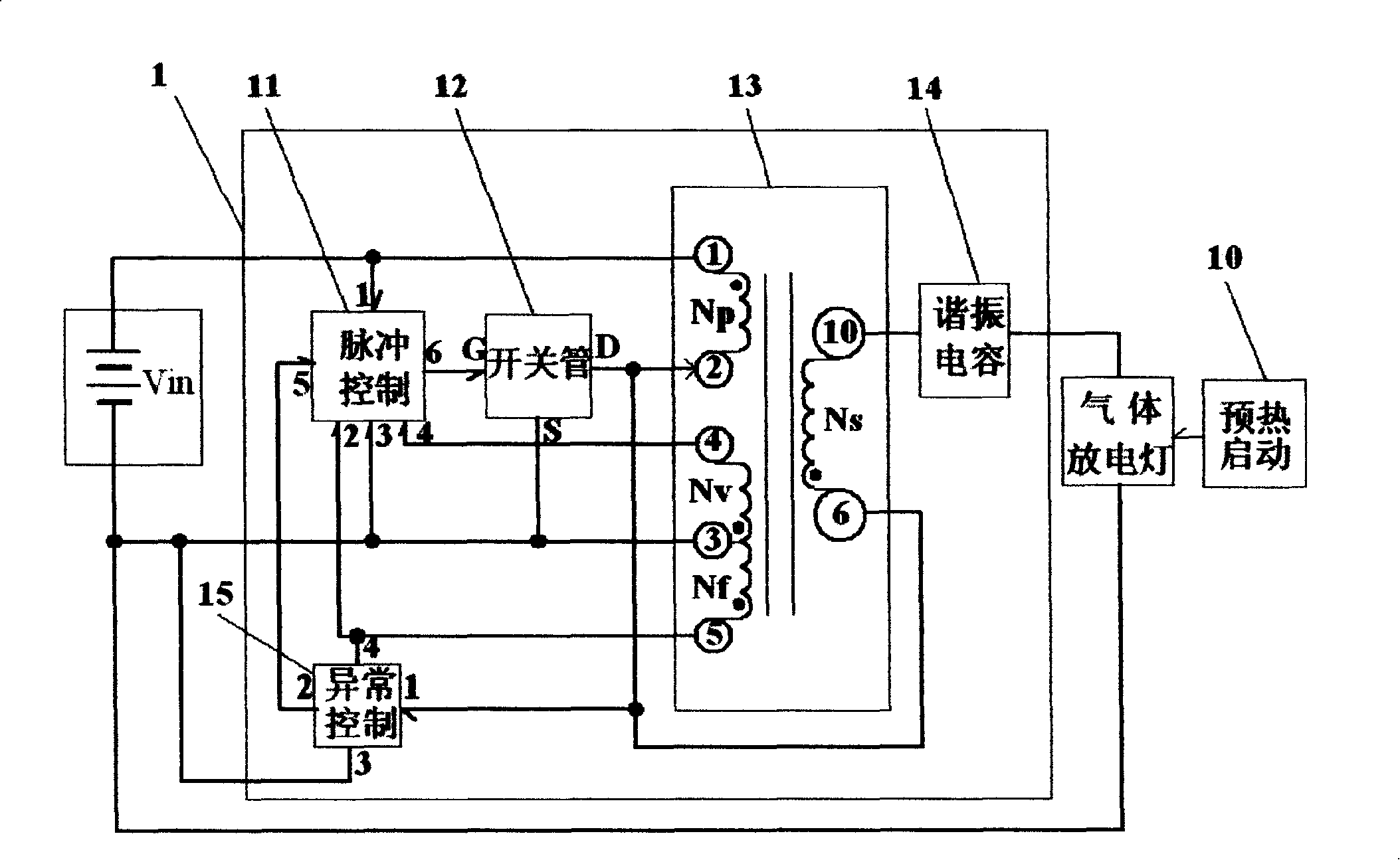
[0123] At first introduce the first embodiment of the device of the present invention, refer to figure 1 . figure 1 The driving device 1 of the gas discharge lamp shown is used to drive the gas discharge lamp with high-frequency AC to make it emit light. The high-frequency AC drive process uses a single resonant circuit; to drive the gas discharge lamp, there is no other double switch tube There are two resonant frequency problems in the circuit (half-bridge circuit), and the power control circuit can stabilize the output power under a wide voltage, and at the same time avoid the saturation of the magnetic core, thereby greatly improving the life of the circuit; the device 1 mainly includes : T...


PUM


Abstract

The invention discloses a plan for a driver (a ballast) of a gas discharge lamp, which is a device that is arranged on a single resonant circuit. The device utilizes a clockwise method and a flyback method simultaneously, also utilizes a resonant circuit to generate a high frequency alternating current power source for driving the gas discharge lamp, and comprises a transformer, a switch tube, a resonant capacitance, a pulse control circuit and an abnormity control circuit; wherein, the transfomer generates high frequency alternating current under the action of the switch tube, and makes the circuits generate resonance under the action of the resonant capacitance for outputting high frequency quasi sine wave. When controlled by the pulse control circuit, the transformer also outputs basically constant high frequency power within the range of wide voltage inputting. When alternating current is inputted, the device also comprises a rectifying circuit, a filtering circuit, a power factor correction circuit, etc.

Description

technical field [0001] The invention relates to a circuit structure of a driving device of a gas discharge lamp, in particular to a circuit structure of a transformer in the driving device of a gas discharge lamp. Background technique [0002] In the driving technology of the gas discharge lamp, in order to improve the efficiency (that is, save electricity) and reduce the size, a high-frequency switching method is usually used. Commonly used circuits are: half-bridge circuit, full-bridge circuit and push-pull circuit, etc.; such as the INVERTER (inverter) of LCD backlight adopts low-voltage full-bridge inverter circuit or push-pull inverter circuit (requires secondary power conversion); energy saving High-frequency electronic ballasts for lamps and fluorescent lamps basically use half-bridge circuits; [0003] Sampling half-bridge (self-excited) circuit electronic ballast oscillation frequency is very discrete, the quality of batch products is difficult to control; the outp...

Claims


Application Information

Patent Timeline
IPC IPC(8): H05B41/14H01F38/10H05B41/24H05B41/36H02M1/00H02M1/12
CPCY02B20/202Y02B20/00
Inventor 叶建国
Owner 叶建国
Learn More