
7A04 aluminum alloy casing body parts multi-functional die forging technique and mold

A multi-directional die forging, aluminum alloy technology, applied in the direction of manufacturing tools, metal processing equipment, forging/pressing/hammer devices, etc., to achieve the effect of improved plastic forming performance, small allowance and tolerance

Inactive Publication Date: 2008-07-09
HUAZHONG UNIV OF SCI & TECH
View PDF0 Cites 42 Cited by
  • Summary
  • Abstract
  • Description
  • Claims
  • Application Information

AI Technical Summary

Problems solved by technology

[0004] The present invention provides a multi-directional die forging process for 7A04 aluminum alloy casing parts, and provides a multi-directional die forging die for realizing the multi-directional die forging process, with the purpose of effectively overcoming the problems existing in the existing open die forging process and isothermal die forging process question

Method used


Image

  • 7A04 aluminum alloy casing body parts multi-functional die forging technique and mold
  • 7A04 aluminum alloy casing body parts multi-functional die forging technique and mold
  • 7A04 aluminum alloy casing body parts multi-functional die forging technique and mold

Examples


Embodiment 1

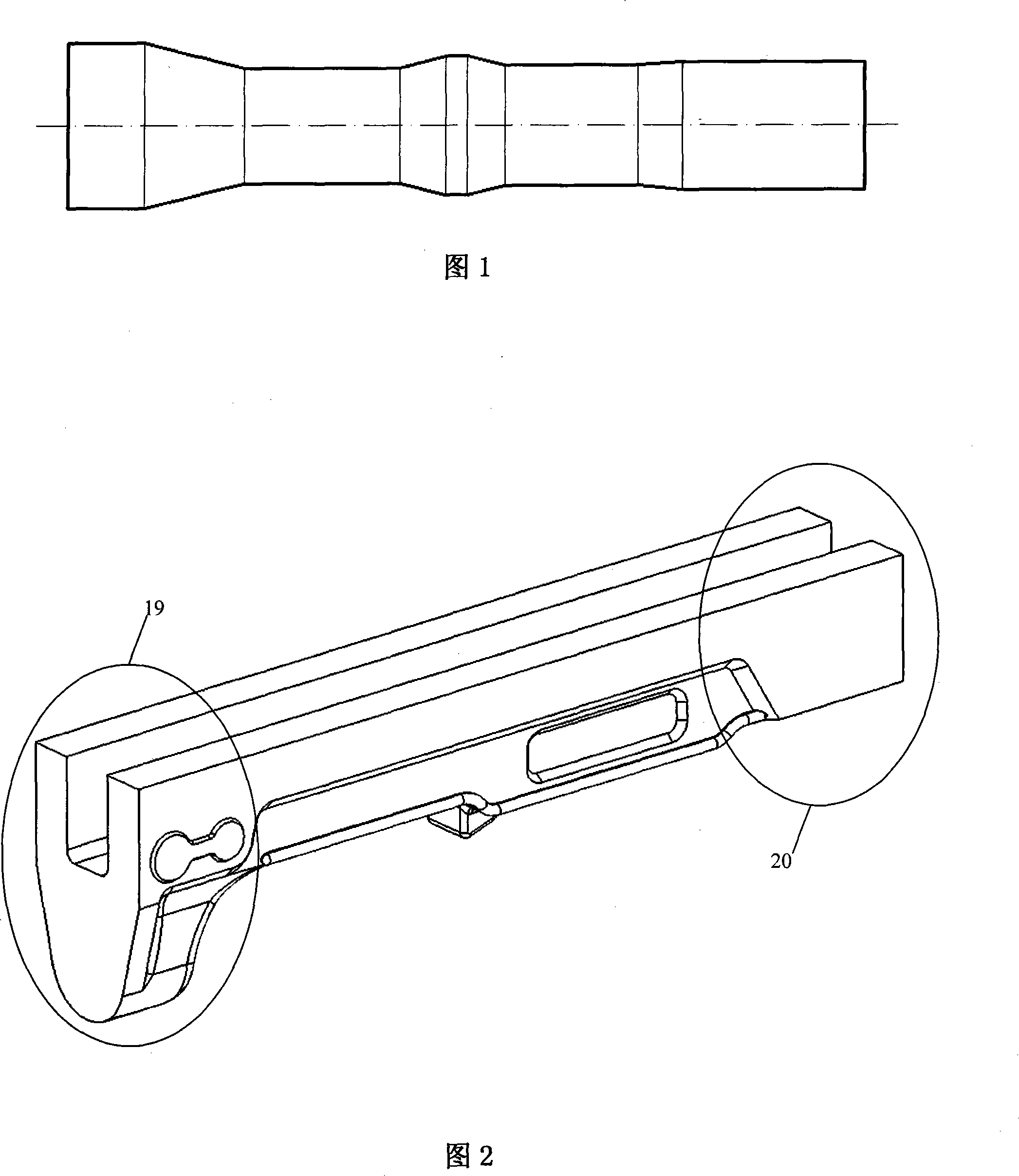
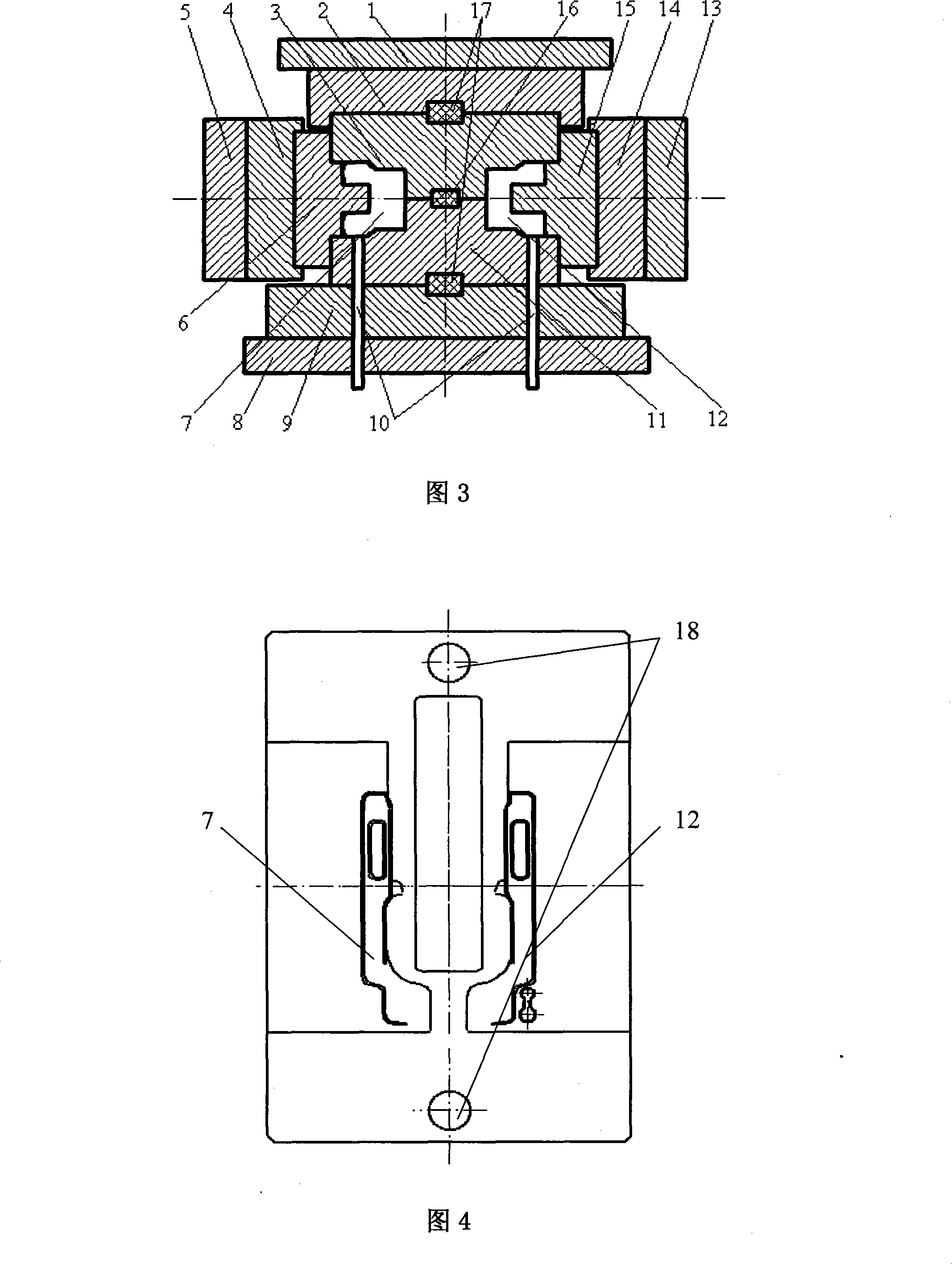
[0033]The multi-directional die forging process of a certain type of casing body forging is as follows: Step 1: Put the 7A04 aluminum alloy roll forging blank heated to 450°C (as shown in Figure 1) into the pre-forging die on the left side of the lower half die 11 In the chamber 7, the upper die base 2 and the upper half die 3 go down with the main slider 1 of the press until the blank is flattened and closed with the lower half die 11, and then the pre-forging punch 6 follows the left slider 5 to the right Move and extend into the pre-forging die cavity 7 to cause back-extrusion deformation of the blank. When the upper and lower shoulders of the pre-forging punch 6 are in contact with the left side of the upper and lower half die modules, the temperature of the upper and lower half dies is 200°C. The pre-forging forming force is 3000KN, the pre-forging punch 6 moves to the left with the left slider 5, withdraws from the pre-forging and the pre-forging die cavity 7, and returns...

Embodiment 2

[0035] The first step: put the 7A04 aluminum alloy blank heated to 430°C into a mold at 220°C for pre-forging; the second step: put the aluminum alloy pre-forging whose temperature is lowered to 350°C into a mold at 220°C for final forging . The rest of the details are the same as in Example 1.


PUM


Abstract

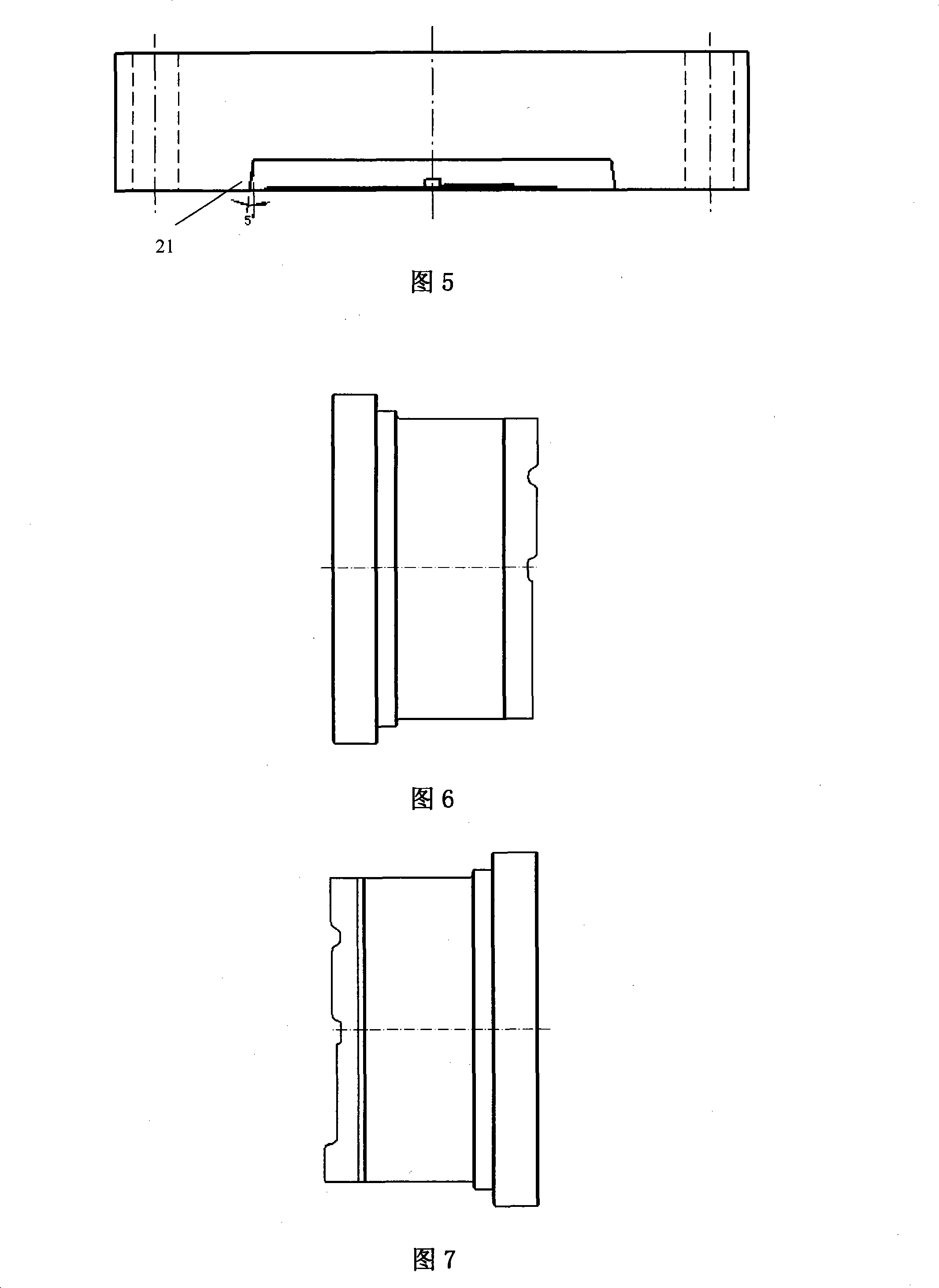
A multi-direction forging technique and die for a 7A04 aluminum alloy cartridge receiver body part belongs to the technical field of metal material plastic forming and aims at effectively overcoming the problems of the existing opening-die forging technique and isothermal-die forging technique. The order of the multi-direction forging technique of the invention includes the steps of baiting, heating, rough making, reheating and multi-direction forging. The multi-direction forging relates to (1) using a multi-direction die forging die to pre-forge and form a heated 7A04 aluminum alloy roll forging rough;(2) then suing the multi-direction die forging die to realize finally forge to forge a die forging element. The invention multi-direction forging die includes symmetrical upper half and lower half concave model, a pre-forging convex model, a final-forging convex model, a fixing plate for the pre-forging convex model, a fixing plate for the final-forging convex model and a model frame consisting of an upper model seat and a lower model seat. The invention has the advantages of reasonable technique flow, stable technique parameter and performance, simple structure of the die, convenient manufacture, mounting and use, reliable work. And the invention can greatly reduce the friction resistance between a forging element and a die chamber, improve the surface quality of the forging element and remarkably improve the service life of the die.

Description

technical field [0001] The invention belongs to the technical field of plastic forming of metal materials, and in particular relates to a multi-directional die forging production process and a mold for 7A04 aluminum alloy case body parts of firearms. Background technique [0002] 7A04 aluminum alloy has high specific strength and specific stiffness, but poor plasticity, large flow resistance of plastic deformation, and strong speed sensitivity. At present, the domestic military industry system for the 7A04 aluminum alloy casing body parts, the traditional method is to use the die forging hammer to open the die forging process, and the process flow is blanking→heating→blank making→pre-forging→heating→finish forging → trimming. The main problems in the process are that the flash metal loss is large, the machining allowance and forging tolerance are large, and the material utilization rate is only 41.4%. Strong and cause cracks on the surface of forgings. Liu Chuanlin, Cao Y...

Claims


Application Information

Patent Timeline
IPC IPC(8): B21J5/02B21J13/02
Inventor 夏巨谌胡国安王新云邓磊冀东生
Owner HUAZHONG UNIV OF SCI & TECH
Learn More