Pneumatic valve

An air-controlled valve and valve body technology, applied in sliding valves, valve details, valve devices, etc., can solve the problems of easy failure, high labor intensity and high cost, and achieve the goal of improving response speed, reducing labor intensity and improving service life. Effect

Active Publication Date: 2008-07-09
WUJIANG WANGONG ELECTROMECHANICAL EQUIP
View PDF1 Cites 20 Cited by
  • Summary
  • Abstract
  • Description
  • Claims
  • Application Information

AI Technical Summary

Problems solved by technology

Five pulses of air flow complete the whole molding process of the molding machine, and the control process is complicated; because the valve plate needs to bear the back pressure generated by the compressed air, the valve plate is very easy to wear; in addition, the wear of the valve plate also produces a large frictional force , so that the valve plate cannot rotate and affect the work of the molding machine; and the structure of this mechanism is complex, the maintenance is labor-intensive and time-consuming, which affects the efficiency of the machine, and sometimes it takes several hours to troubleshoot
The disadvantage of this kind of valve is: when the valve is closed or partially closed, the valve core bears the back pressure of the fluid, which increases the pressure on the side of the valve core facing the fluid outlet, and the valve core is easy to wear after long-term use, which affects the sealing effect and service life; Need to contact the two-position four-way solenoid valve to control the pressure, not only the control is complicated but also the cost is high; there are other valves that have been improved on this basis, and the spring is used to accelerate the reset of the spool, but the spring itself will be affected by the service life and air humidity , is prone to failure, so the effect is not ideal

Method used


Image

  • Pneumatic valve

Examples


Embodiment Construction

[0021] The content of the invention will be described in detail below in conjunction with the accompanying drawings.

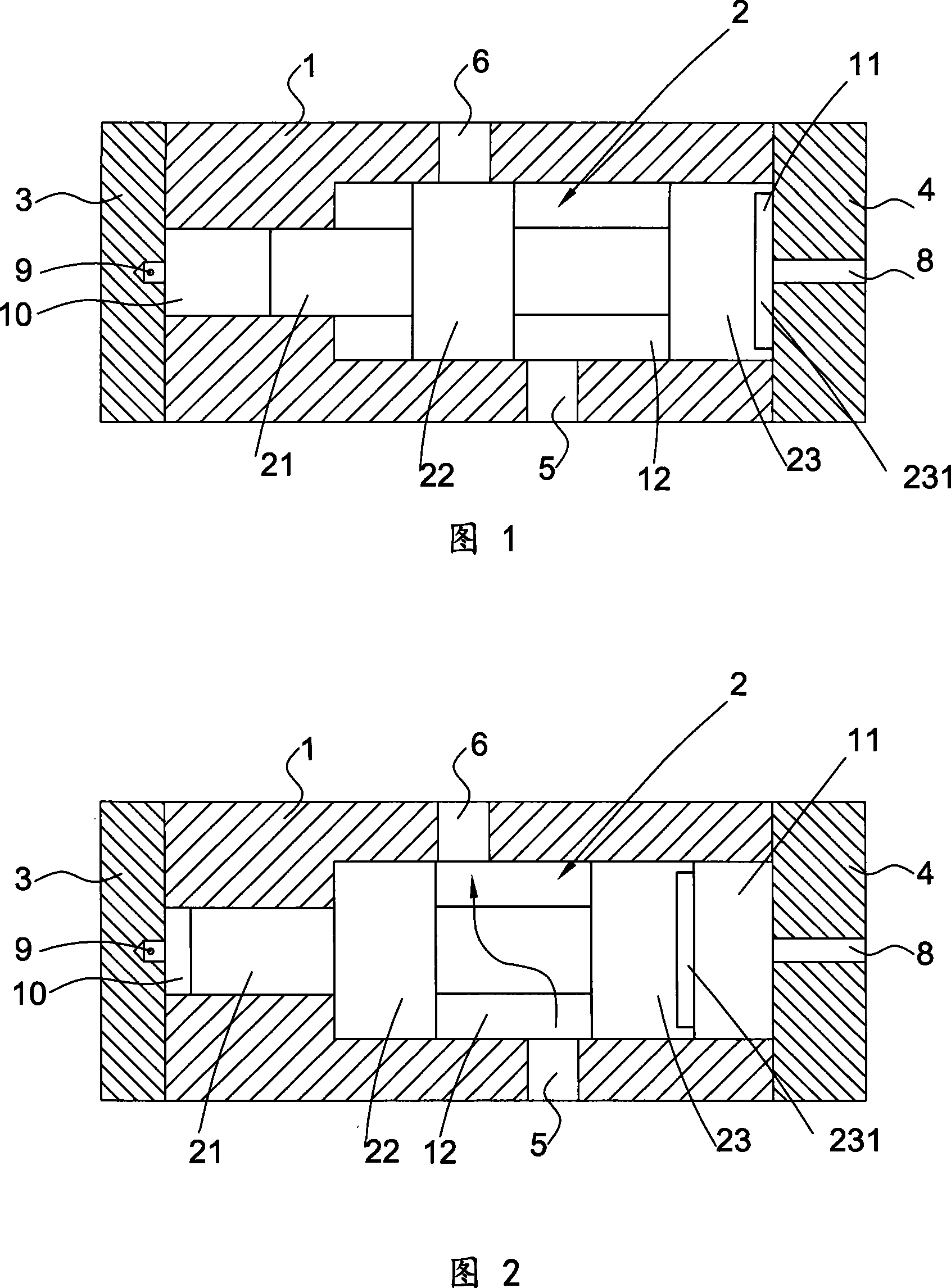
[0022] As shown in Figure 1, an air-operated valve includes a valve body 1, a valve core 2 slidably arranged in the inner cavity of the valve body 1, and two valve cores that are respectively sealed and fitted on the valve body 1. The front end cover 3 and the rear end cover 4 of end (the left side among the accompanying drawings 1 is the "front" side described in the description, and the right side among the accompanying drawings 1 is the "rear" side described in the description). In order to better improve the reaction speed of the valve core 2 and reduce the friction between the valve core 2 and the valve body 1, a very small metal gap is used between the valve core 2 and the valve body 1 to seal and cooperate, and the valve core 2 and the valve body 1 Adding some lubricating oil between them can make the valve core 2 move more smoothly and the sealing effe...


PUM


Abstract

A pneumatic valve comprises a valve body, a valve core, a front end cover and a rear end cover. The valve body is provided with a fluid inlet and a fluid outlet on the two opposite lateral walls. Air holes are opened on the front end cover and the rear end cover respectively. The valve core has a first end part, a second end part and a closed part, which are hermetically engaged with the inner wall of the valve body respectively. The first end part, the valve body and the front end cover circle around to form a first gas chamber. The second end part, the valve body and the rear end cover circle around to form a second gas chamber. The area of front end surface of the first end part is smaller than that of rear end surface of the second end part. The first gas chamber is communicated with a pneumatic reset system by a gas hole on the front end cover. The second gas chamber is communicated with a pneumatic control system by a gas hole on the rear end cover. The reset system has a constant pneumatic pressure. The invention uses the differential pneumatic valve to control the fluid flow, exerts no back pressure on the valve core, and has the advantages of high reliability, good reaction sensitivity and long service life.

Description

technical field [0001] The invention belongs to a sliding valve, in particular to an air-controlled sliding valve which uses the principle of air pressure difference to control the movement of the valve core to realize the opening and closing of the valve. Background technique [0002] The molding process of the existing molding sand molding machine is as follows: first, the molding sand is compacted by the vibrating cylinder, then the pressure head cylinder pushes the pressure head to rotate 90°, the compaction cylinder rises to further compact the molding sand in the sand box, and finally the compaction cylinder descends, The pressure head cylinder resets. Usually, this process is controlled by the butterfly valve. The pulsed airflow controls the reciprocating motion of the cylinder, thereby driving the movement of the rack and the sector gear. The swing of the sector gear realizes the directional rotation of the rotating valve plate. 60° to realize one movement of the mo...

Claims


Application Information

Patent Timeline
Patent Type & Authority Applications(China)
IPC IPC(8): F16K3/02F16K31/12F15B13/02
Inventor 郑志刚
Owner WUJIANG WANGONG ELECTROMECHANICAL EQUIP
Why Eureka
Try Eureka