
Heterodyne interferometer measuring system for measuring displacement and its measurement method

A technology of heterodyne interferometry and measurement system, which is applied in the direction of measuring devices, instruments, and optical devices, etc., which can solve problems such as the increase in the size of the projection objective lens system and the increase in exposure, so as to reduce costs, simplify the structure, and reduce the number of uses Effect

Active Publication Date: 2008-07-09
SHANGHAI MICRO ELECTRONICS EQUIP (GRP) CO LTD
View PDF1 Cites 39 Cited by
  • Summary
  • Abstract
  • Description
  • Claims
  • Application Information

AI Technical Summary

Problems solved by technology

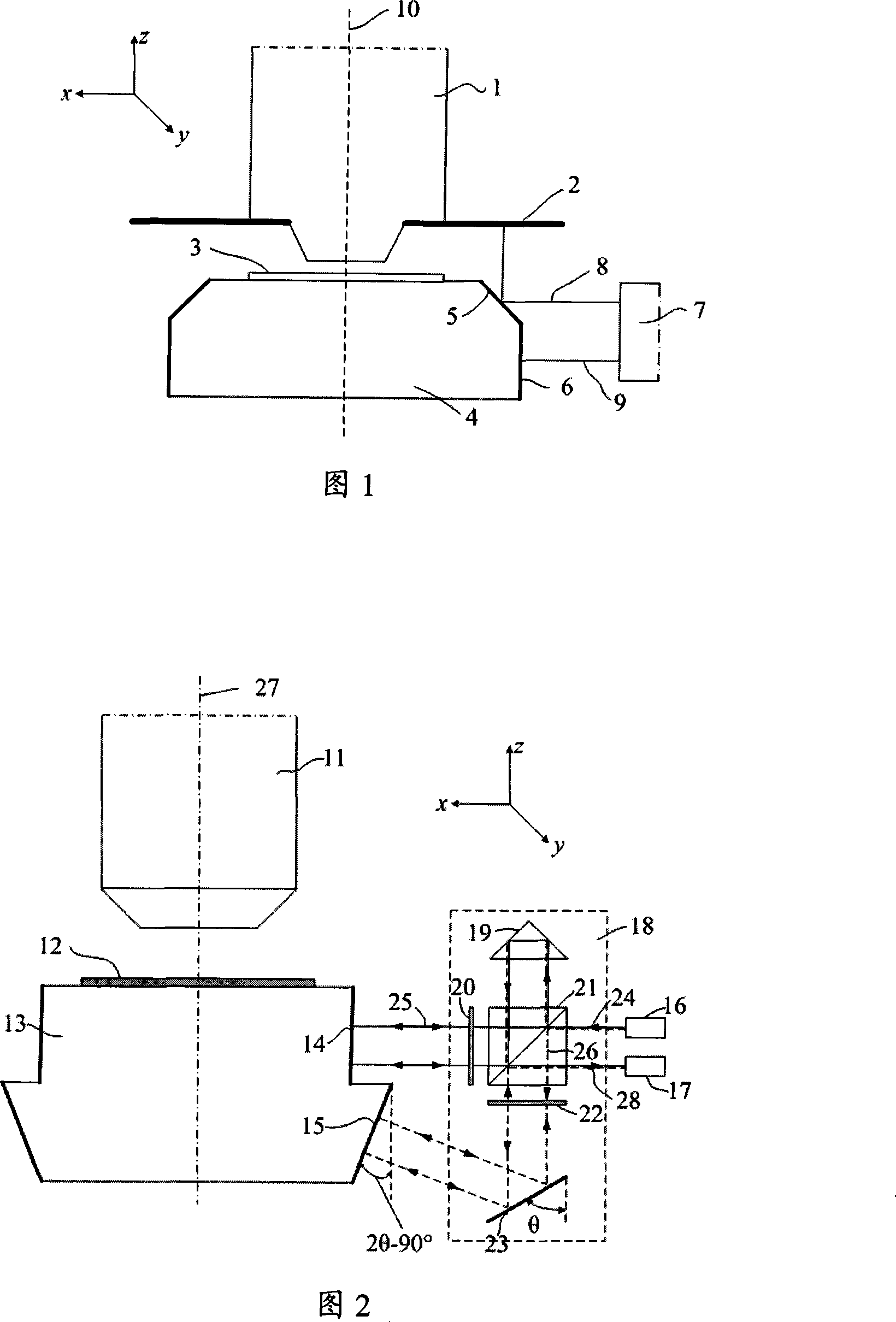
[0004] The interferometric measurement system proposed in the prior art 1 can accurately measure the displacement of the workpiece table 4 in the z direction, but since the reflector 2 needs to have the same size as the travel of the workpiece table 4 in the x direction, the projection objective lens system needs to be in the x direction. The size in the direction becomes larger, which is not conducive to installation
In addition, in order to achieve a smaller feature size, the size of the projection objective lens is constantly increasing. If there are larger flat mirrors installed on both sides, this will increase the difficulty in achieving smaller feature size exposure.

Method used


Image

  • Heterodyne interferometer measuring system for measuring displacement and its measurement method
  • Heterodyne interferometer measuring system for measuring displacement and its measurement method
  • Heterodyne interferometer measuring system for measuring displacement and its measurement method

Examples


Embodiment approach

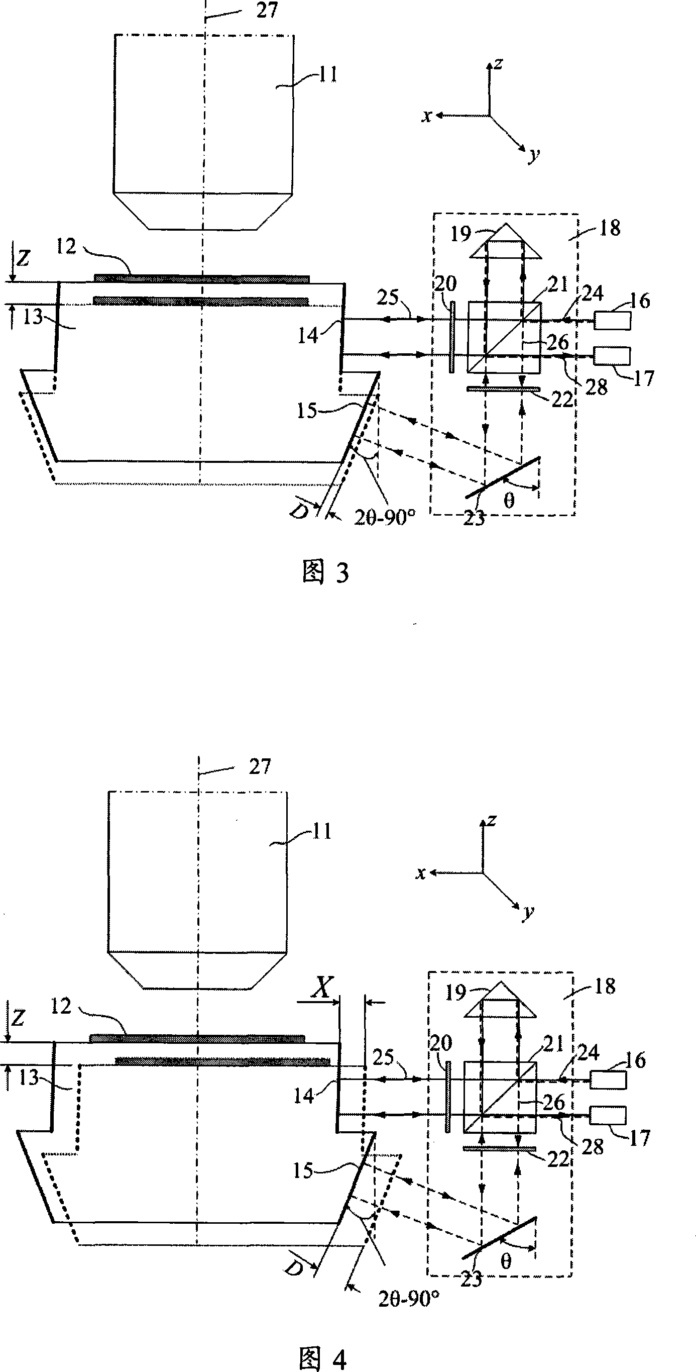
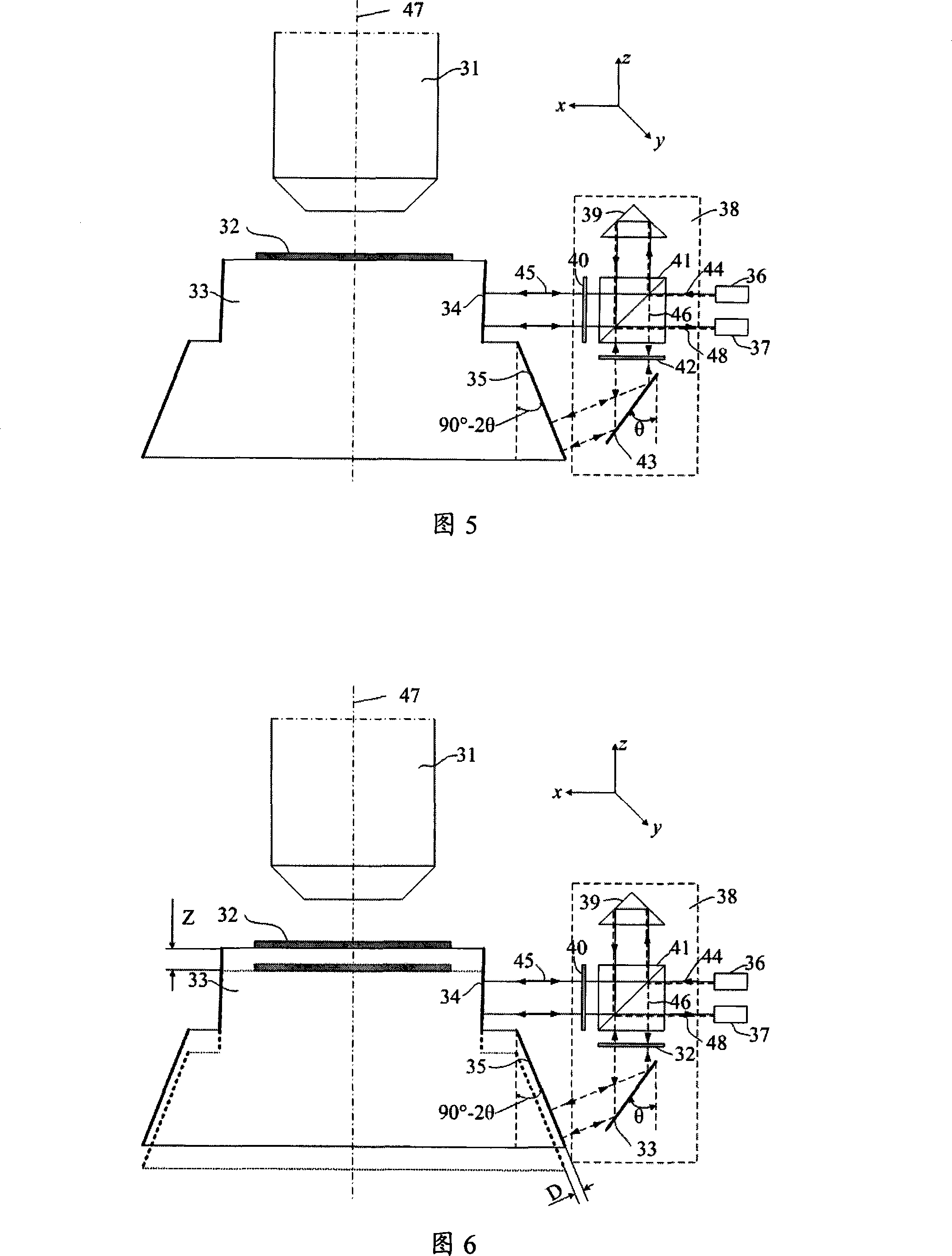
[0042] As shown in FIG. 2 , it is a specific measurement embodiment of a heterodyne interferometry system for measuring displacement provided by the present invention. Interferometer 18 comprises polarizing beamsplitter prism 21, corner cube prism 19, quarter-wave plate 20 and 22, reference plane reflector 23, the included angle of reference plane reflector 23 and optical axis direction is θ (45 ° < θ < 90°). The laser 16 is used to provide interferometric laser light, and the photoelectric conversion element 17 is used to receive the measured interference signal. The workpiece table 13 below the projection objective lens 11 carries the silicon wafer 12 that needs to be exposed, and the first plane reflector 14 and the second plane reflector 15 are installed on the side of the workpiece table 13, and the clamp between the second plane reflector 15 and the optical axis The angle is 2θ-90°.

[0043] The working principle and steps of the measurement system are as follows: the ...


PUM


Abstract

The invention relates to a heterodyne interferometer measurement system for measuring displacement and a measuring method thereof. The measurement system comprises a workbench reflector set and a laser heterodyne interferometer; the workbench reflector set comprises a first plant reflector disposed on the lateral side of the workbench and parallel with an optical axis, and a second plant reflector having certain angle with the optical axis; and the laser heterodyne interferometer comprises a polarization slitting prism, a cube corner prism, a reference plane reflector having certain angle with the optical axis, and two quarter-wave plates. The measuring method comprises the following steps of: allowing a reference beam and a measuring beam generated by a laser passing through the polarization slitting prism to respectively enter a photoelectric conversion element after multiple reflections and transmissions, processing to obtain an optical path difference (OPD), and then obtaining Z-axis displacement Z of the workbench. The invention needs not to use the plane reflectors disposed at two sides of a projection objective lens, resulting in simple structure; and needs not to increase extra size of the projection objective lens at X-axis direction. The cost of the measurement system is reduced due to less number of the used plane reflectors.

Description

technical field [0001] The invention relates to a heterodyne interferometric measurement system for measuring displacement and a measurement method thereof. Background technique [0002] As the size of lithographic features decreases, the depth of focus becomes smaller and smaller. In order to enable silicon wafers to be exposed within the focal depth range, the Z-direction (along the optical axis) position measurement of the workpiece table is indispensable to ensure the excellent lithography performance of the lithography machine. [0003] The Z-direction position of the workpiece table can be accurately measured by using a laser heterodyne interferometry system (see prior art 1, Erik R. Loopstra, "Method and apparatus for repeatedly projecting mask pattern on a substrate, using a time-saving height measurement”, US Patent Application No.: 6208407). FIG. 1 shows the measurement system proposed in the prior art 1. As shown in FIG. The silicon wafer 3 is placed on the wor...

Claims


Application Information

Patent Timeline
IPC IPC(8): G01B9/02G01B11/02
Inventor 马明英段立峰
Owner SHANGHAI MICRO ELECTRONICS EQUIP (GRP) CO LTD
Learn More