Non-refigeration method for reducing temperature sensitivity of fiber optical gyroscope scale factor

A technology of temperature sensitivity and fiber optic gyro, which is applied in the field of signal processing, can solve the problems of affecting temperature performance, reducing reliability, increasing system complexity, etc., to achieve the effect of reducing temperature sensitivity, reducing heat generation, and improving thermal environment

Inactive Publication Date: 2008-07-09
ZHEJIANG UNIV
View PDF0 Cites 17 Cited by
  • Summary
  • Abstract
  • Description
  • Claims
  • Application Information

AI Technical Summary

Problems solved by technology

The total power consumption of a typical fiber optic gyroscope is less than 5 watts, while the cooling power consumption of the light source is about 2 watts, and the cooling circuit occupies nearly half of the power consumption of the system
[0007] The second problem is that the power consumption of the cooling circuit is finally converted into the same amount of heat dissipated inside the system, thereby deteriorating the thermal environment inside the fiber optic gyroscope and affecting its temperature performance
Especially when operating in a high-temperature environment, in order to keep the temperature of the light source constant, the refrigerator cools and generates heat, and the heat emitted further deteriorates the internal thermal environment and increases the internal temperature. The increase in temperature requires more cooling capacity of the refrigeration circuit, and more cooling means As th

Method used


Image

  • Non-refigeration method for reducing temperature sensitivity of fiber optical gyroscope scale factor
  • Non-refigeration method for reducing temperature sensitivity of fiber optical gyroscope scale factor
  • Non-refigeration method for reducing temperature sensitivity of fiber optical gyroscope scale factor

Examples


Embodiment Construction

[0033] Below in conjunction with accompanying drawing and embodiment the present invention will be further described

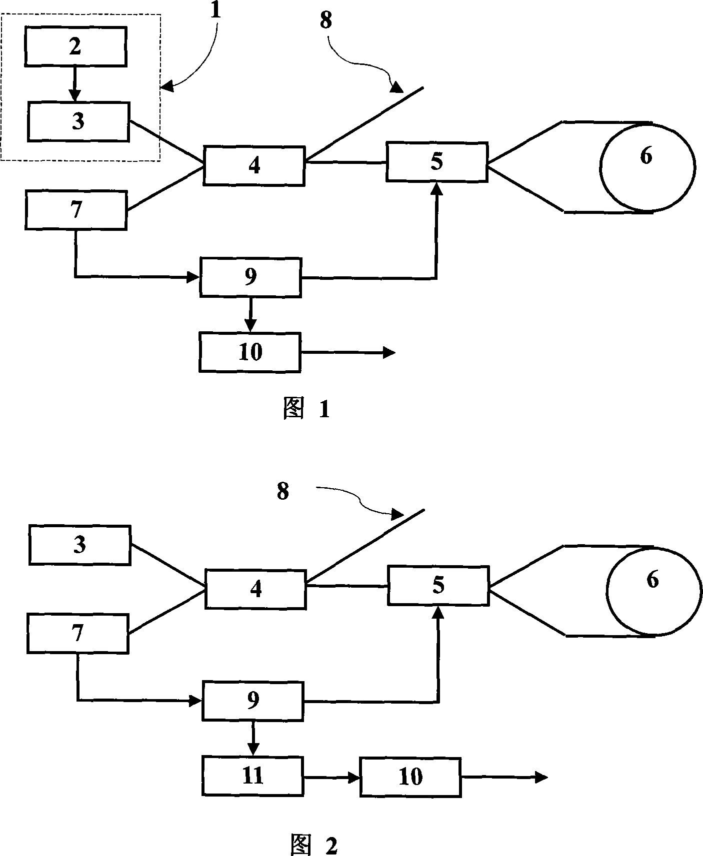
[0034] As shown in Figure 1, it is a schematic block diagram of an optical fiber gyroscope with a cooling circuit light source; wherein 1 is a light source module used by an optical fiber gyroscope, which is composed of a cooling circuit 2 and a light source 3, and the cooling circuit 2 makes the temperature of the light source constant through temperature control, thereby The stability of the average wavelength of the output light is guaranteed; after the light source outputs light, it enters the fiber coupler 4, and the fiber coupler divides the light into two parts, one part is output to the phase modulator 5, the other part is output to the dead end fiber 8, and the other part is output to the dead end fiber 8. The light of the head optical fiber 8 is an unused part of the fiber optic gyro; the phase modulator 5 receives the light of the fiber coupler 5, an...


PUM


Abstract

The invention discloses a method for reducing temperature sensitivity of optical fiber gyroscope scale factors without a refrigerating light source. The method comprises the following steps of: removing a light source refrigerating circuit from an optical fiber gyroscope, controlling the temperature of the light source of the optical fiber gyroscope via an incubator according to a series of pre-selected temperature points, measuring the average wavelength of the light outputted from the light source with a spectrometer to obtain a table of the average wavelength and the temperature points, and placing the table into a memorizer of a table look-up module in correction step; adding average wavelength correction step, real-time collecting a temperature signal with a thermometer, looking up the table to obtain the average wavelength value under certain temperature according to the temperature signal, and performing average wavelength correction to the original output data of the optical fiber gyroscope according to the value. The corrected data is used as new output data of the optical fiber gyroscope, and the scale factor of the new output data is irrelevant to the average wavelength, so as to reduce the temperature sensitivity of the scale factor of the optical fiber gyroscope without refrigerating light source, thereby simplifying the system, reducing power consumption and heating value, improving the internal thermal environment, and improving the reliability.

Description

technical field [0001] The invention relates to a signal processing method in an optical fiber gyroscope sensor, in particular to a light source non-cooling method for reducing the temperature sensitivity of the optical fiber gyroscope scale factor. Background technique [0002] The fiber optic gyroscope is an angular velocity sensor based on the optical Segneck effect. The angular velocity information of the platform where the fiber optic gyroscope is located is obtained by detecting the Segneck optical phase difference between the light beams propagating along two reciprocal optical paths of the fiber optic interferometer. . Because the fiber optic gyroscope is an all-solid-state sensor, it can be started quickly and has a large bandwidth, so it is widely used as a new angular velocity sensor. The most typical application is in the aerospace application system, as an angular velocity information sensor in navigation calculation and attitude control. The proportional coef...

Claims


Application Information

Patent Timeline
IPC IPC(8): G01C19/72G01C25/00H05B37/02
CPCY02B20/42Y02B20/40
Inventor 陈杏藩刘承舒晓武胡慧珠
Owner ZHEJIANG UNIV
Why Eureka
Try Eureka