Light optics system for microlithography

An illumination optical system and optical system technology, applied in the field of microlithography, can solve problems such as large loss, spectral line energy that cannot meet the requirements of exposure, and mercury lamp energy not concentrated, so as to achieve low energy, improve uniform light effect, Guaranteed the effect of the size of the lighting field

Active Publication Date: 2008-07-09
SHANGHAI MICRO ELECTRONICS EQUIP (GRP) CO LTD
View PDF3 Cites 8 Cited by
  • Summary
  • Abstract
  • Description
  • Claims
  • Application Information

AI Technical Summary

Problems solved by technology

[0003] However, because the energy of the mercury lamp is not concentrated, the loss is large. After passing through multiple sets of relay lenses and homogenizers, the energy of the obtained spectral lines often cannot meet the requirements of exposure.
US20050083685 adopts the structure of two sets of mercury lamps, splicing three quartz rods to uniform light, although the number of light sources has increased, but the light from the mercury lamps directly enters the quartz rods, there is still a lot of energy loss, and the first and second rods The coupling between the quartz rod and the third quartz rod also has the problem of coupling efficiency

Method used


Image

  • Light optics system for microlithography
  • Light optics system for microlithography
  • Light optics system for microlithography

Examples


Embodiment Construction

[0023] The specific embodiments of the present invention will be further described below in conjunction with the accompanying drawings.

[0024] The technical solution of the schematic diagram of the present invention has been provided, and the light propagation path and the specific implementation of the optical system are described below:

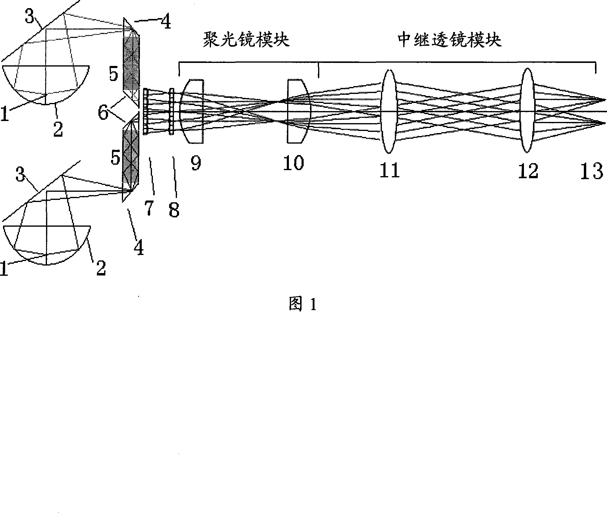
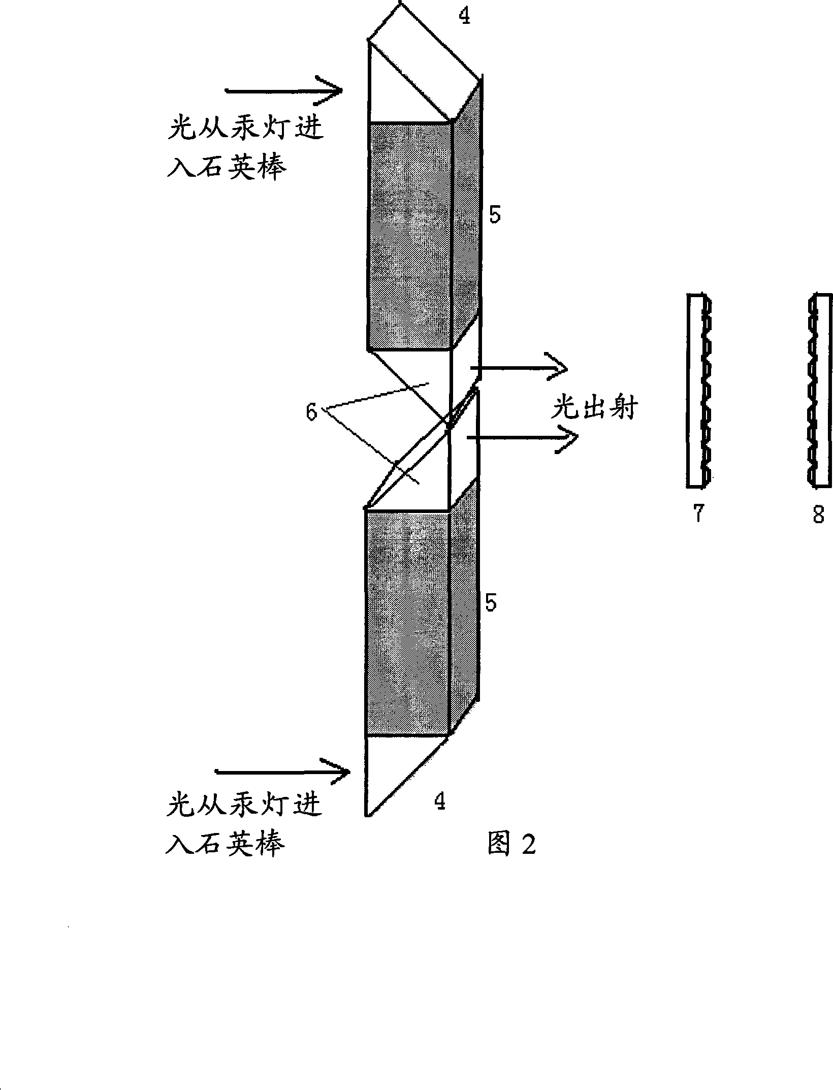
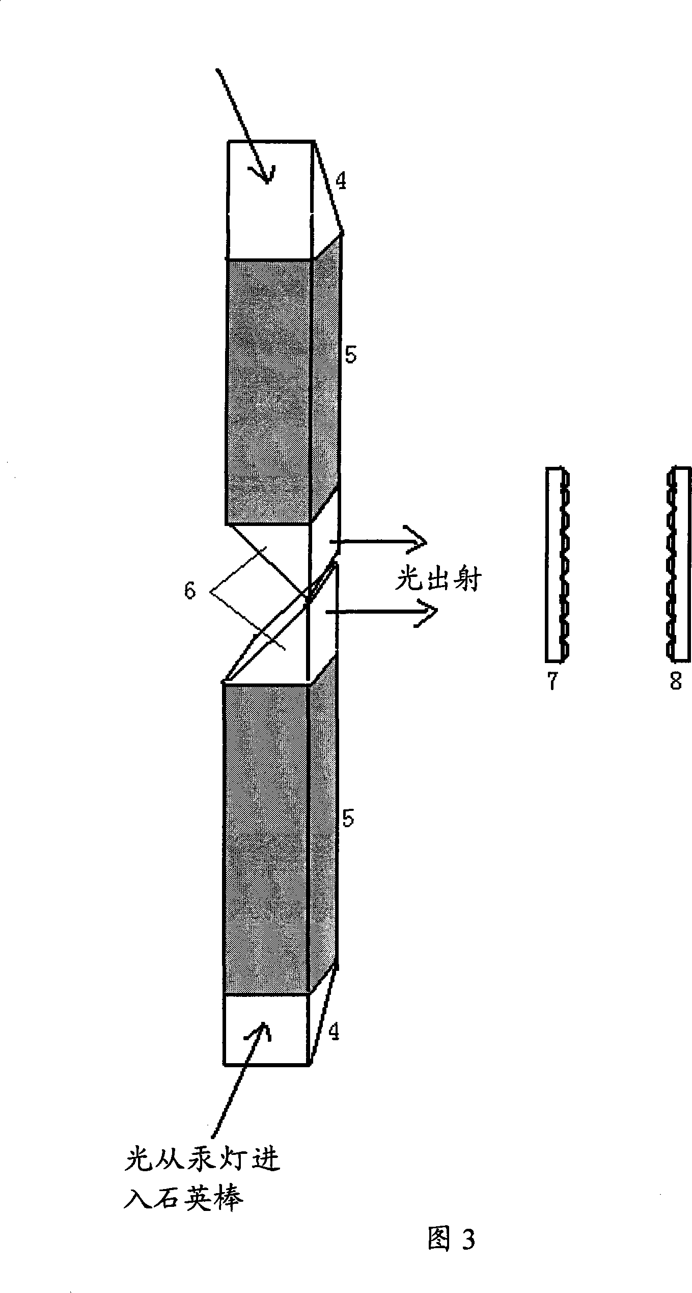
[0025] Fig. 1 (Fig. 1 is the optical path diagram of the embodiment of the present invention adopting two high-pressure mercury lamp light sources) the high-pressure mercury lamp light source 1 filament position is at the focal point F1 inside the ellipsoid reflector 2, so that the image of the light source can be guaranteed to be at the focal point Correct position of F2. The positions of the two mercury lamps can be placed according to actual needs, but after reflection by the reflector 3, it should be ensured that the focus of the ellipsoidal reflector is at the entrance of the quartz rod 5. The light passes through the incident end o...


PUM


Abstract

The invention discloses an illumination optical system for micro photoetching. A plurality of mercury lamps are used as light sources, thereby greatly improving the total light energy content of the light sources without causing the energy content of a single light source to be too large; and a plurality of quartz rods are used, and two sets of micro lens arrays are used as a light homogenizer, thereby effectively improving illumination uniformity and light intensity of an illumination field. The invention can be an illumination system for 365-465nm photoetching devices or other illumination systems.

Description

technical field [0001] The present invention relates to microlithography, and more particularly, to a set of illumination optical systems in microlithography equipment. Background technique [0002] In the existing photolithography method, the optical system using high-pressure mercury lamp illumination mainly exposes g (436nm) h (405nm) i (365nm) three lines, and obtains a certain photoresist pattern on the silicon wafer coated with photoresist, and then The same photoresist pattern is obtained on the silicon wafer through etching and other steps. [0003] However, because the energy of the mercury lamp is not concentrated and the loss is large, after passing through multiple sets of relay lenses and homogenizers, the energy of the obtained spectral lines often cannot meet the requirements of exposure. US20050083685 adopts the structure of two sets of mercury lamps, splicing three quartz rods to uniform light, although the number of light sources has increased, but the lig...

Claims


Application Information

Patent Timeline
Patent Type & Authority Applications(China)
IPC IPC(8): G03F7/20G02B27/09
Inventor 张祥翔
Owner SHANGHAI MICRO ELECTRONICS EQUIP (GRP) CO LTD
Why Eureka
Try Eureka