

A permanent magnet DC motor
A permanent magnet DC, motor housing technology, applied in electric components, electrical components, electromechanical devices, etc., can solve the problems of inaccurate motor commutation, large rotor temperature rise, affecting motor performance, etc., and achieve high reliability. , the effect of stable work
- Summary
- Abstract
- Description
- Claims
- Application Information
AI Technical Summary
Problems solved by technology
Method used
Image

Examples
Embodiment Construction
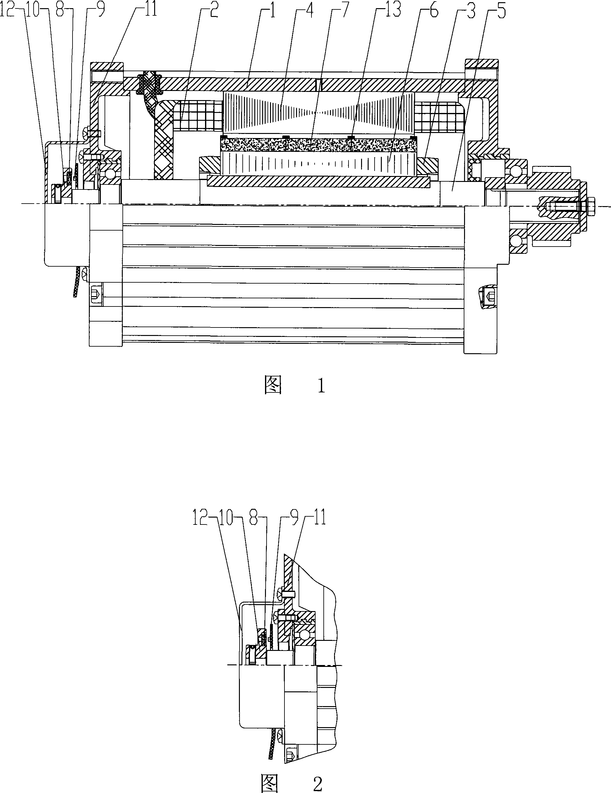
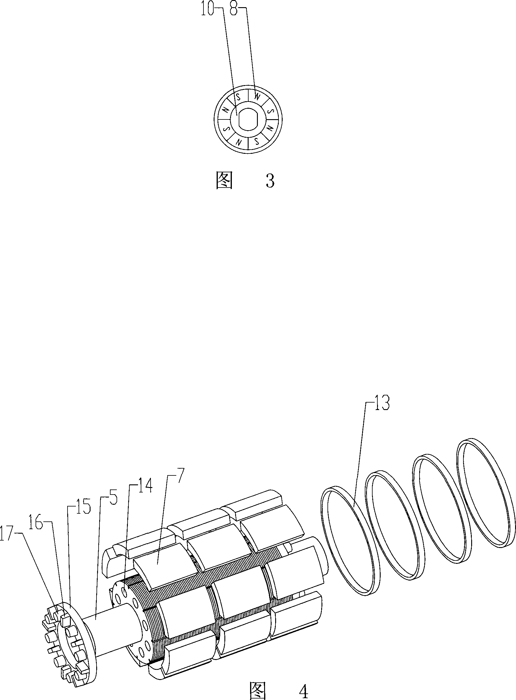
[0018] In conjunction with Fig. 1, Fig. 2, Fig. 3, Fig. 4 shows: the permanent magnet DC motor of the present embodiment comprises: the stator 2 and the rotor 3 are arranged in the motor housing 1, the winding coil 4 is arranged on the stator core, and the rotor The rotating shaft 5 is provided with a magnetic core made of disc-shaped steel sheets 6 stacked, the rotor magnetic tile 7 is fixed on the periphery of the magnetic core, and the motor is provided with a position sensing element including a sensor magnetic steel 8 and three Hall elements 9 . The sensor magnet 8 is set in the magnet base 10, the magnet base 10 is fixed on the motor shaft 5 protruding from the end cover 11, the sensor magnet and three Hall elements are arranged in the end cover 11 and the dust cover 12 to form a in the cavity.
[0019] The sensor magnet 8 is a magnetic ring formed by splicing a plurality of discrete magnetic poles.
[0020] The magnetic poles of the rotor magnetic tiles are composed of...
PUM
 Abstract
Description
Claims
Application Information