Laser piercing method, and machining apparatus

A technology of laser perforation and processing device, used in laser welding equipment, metal processing equipment, manufacturing tools, etc., can solve the problems of reduced processing efficiency, reduced material utilization, and larger aperture of through holes, and achieves high aperture accuracy and high precision. Productivity, the effect of suppressing expansion

Active Publication Date: 2008-07-09
NISSAN TANAKA
View PDF3 Cites 7 Cited by
  • Summary
  • Abstract
  • Description
  • Claims
  • Application Information

AI Technical Summary

Problems solved by technology

[0013] However, according to the above-mentioned method, it is necessary to provide a groove for discharging the molten material in advance, and there is a problem that the through-hole becomes larger due to the existence of the discharge groove.
[0014] In addition, when performing perforation, if excessive oxidation and combustion reactions occur on the workpiece W, the diameter of the through hole will increase and the material utilization rate will decrease. On the other hand, for example, when the laser is excited in a pulse state , there is the following problem, although the precision of the through-hole diameter is improved, but the processing efficiency is significantly reduced

Method used


Image

  • Laser piercing method, and machining apparatus
  • Laser piercing method, and machining apparatus
  • Laser piercing method, and machining apparatus

Examples


no. 1 approach

[0163] 1 is a diagram showing the state of processing a laser cutting torch 2 and a through hole H according to the first embodiment. The laser cutting torch 2 is provided with a nozzle 3 and a condenser lens 6. The nozzle 3 is formed in a cylindrical shape and passes through the condenser lens. 6 laser light L1 is condensed and irradiated as laser light L2 from the injection hole 3b.

[0164] In addition, the optical axis of the laser light L2 is coaxial with the nozzle 3 to share the axis O1, and the axis O1 is coaxial with the center axis OG of the pressure distribution of the assist gas G injected from the nozzle 3 .

[0165] The assist gas is introduced into the nozzle 3 through the introduction passage 4 and injected from the injection port 3b, and the irradiated laser light L2 melts and evaporates the processed material W by an oxidation reaction to burn.

[0166] In this embodiment, since the machining starting point of the through-hole machining on the workpiece W is ...

Embodiment 1

[0299] Embodiment 1, after the perforation processing of steel plate starts, the axis O1 of laser cutting torch 2 is deviated from the starting point of processing, then, while drawing a circle track around the starting point of processing, rotate the prescribed number of times of rotation N (times), and then return to the starting point of processing, Process through holes.

Embodiment 2

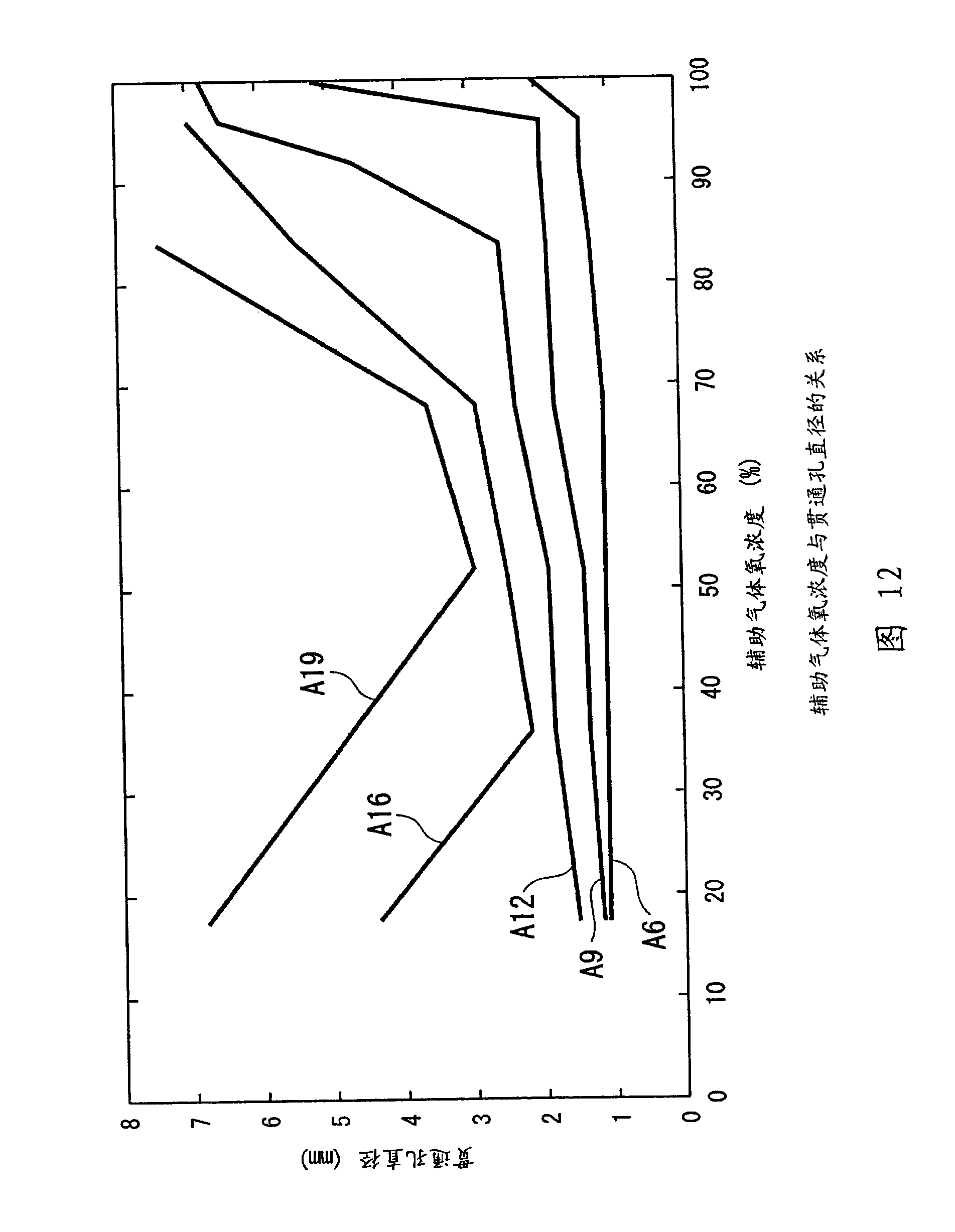
[0300] Example 2 On the basis of the processing conditions of Example 1, the oxygen concentration C of the assist gas G was adjusted to 52.6 (vol%) to process through-holes.


PUM


Abstract

In processing equipment, a machining portion of a subject (W) to be machined is irradiated with a laser beam (L2), an assist gas (G) is jetted toward the machining portion from a nozzle (3) coaxially arranged with the laser beam (L2) to cover the machining portion with the assist gas (G), and a piercing hole (H) is machined at the machining portion. The machining equipment is provided with a control means (10) for machining the piercing hole (H) while shifting the nozzle (3) within a range from a machining start point to 5mm, after starting irradiation of the laser beams (L2).

Description

technical field [0001] The present invention relates to a method of perforating a material to be processed by a laser processing device and a processing device using the perforating method. [0002] This patent application claims priority based on Japanese Patent Application No. 2005-16996 filed in Japan on June 7, 2005, and Japanese Patent Application No. 2006-106982 filed in Japan on April 7, 2006, and the contents thereof are incorporated herein. Background technique [0003] Conventionally, for example, when a laser processing device is used to cut a workpiece such as a steel plate, a small through hole with a diameter of several millimeters is opened by laser drilling at a position serving as a starting point for cutting, and the cutting is performed from this point. [0004] The through hole is very important in improving the processing quality accuracy of the processed material without reducing the material utilization rate, and it is desired to be as small as possibl...

Claims


Application Information

Patent Timeline
Patent Type & Authority Applications(China)
IPC IPC(8): B23K26/38B23K26/14B23K103/04B23K26/382
Inventor 沼田慎治佐野义美
Owner NISSAN TANAKA
Why Eureka
Try Eureka