Electrical gearbox with continuous variation

A gear transmission and electric transmission technology, applied in the direction of motors, electromechanical devices, electric vehicles, etc., can solve problems such as low overall efficiency, and achieve the effect of high overall efficiency and low production cost

Inactive Publication Date: 2008-07-09
佐格·奥登堡 +1
View PDF0 Cites 4 Cited by
  • Summary
  • Abstract
  • Description
  • Claims
  • Application Information

AI Technical Summary

Problems solved by technology

Such a machine has a rather low overall efficiency due to the multiplication of efficiencies of the individual components - internal combustion engine, generator, controller and electric motor

Method used


Image

  • Electrical gearbox with continuous variation
  • Electrical gearbox with continuous variation

Examples


Embodiment Construction

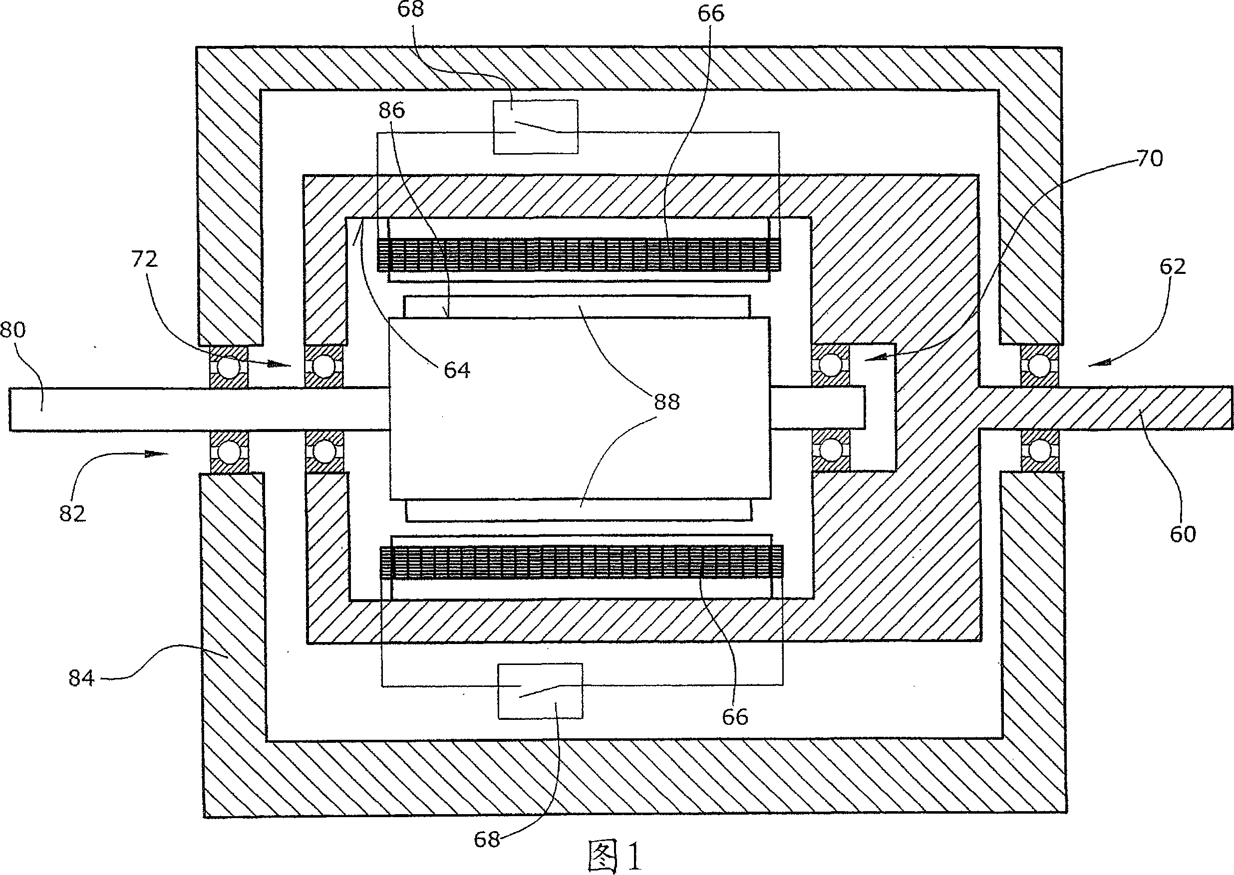
[0026] In a first preferred embodiment, the electric transmission of the invention (FIG. 1) comprises an input shaft 80 connectable to a drive. For example, the drive device can be an internal combustion engine.

[0027] Further, the transmission device (or referred to as a transmission) includes an output shaft 60, and the input shaft 80 and the output shaft 60 are connected through a power transmission device. The input and output shafts are not physically connected. An electric field is established between the input shaft 80 and the output shaft 60 , which induces a torque, which is a drag torque and is load dependent, causing the output shaft 60 to follow the input shaft 80 .

[0028] Since the drag torque of the transmission, like all other mechanical resistances in the transmission, always results in the output shaft 60 being pulled by the input shaft 80, the mechanical efficiency of the transmission is increased as provided by the present invention.

[0029] In order ...


PUM


Abstract

The invention relates to an electric transmission comprising an input shaft (10, 11) adapted to be connected to a control device such as an internal combustion engine. The input shafts (10, 11) are connected to the output shafts (20, 66) through power transmission means (88, 66). Wherein, the power transmission device (88, 66 and 18, 26, 42, 44) includes a magnet (18, 42, 88) connected to the input shaft (10, 11), and the magnet induces electric power to enter and connect to the output shaft (20, 60) Connected coils (26, 66). A magnetic field that rotates the output shaft (20, 60) is generated by switching means (46, 68) connected to the coil (26, 66).

Description

technical field [0001] The invention relates to a continuously variable electric transmission device. Background technique [0002] With traditional gearing, the speed can be varied in steps, with friction clutches or hydraulic clutches used to move the gears in the gearing. Although such transmissions have a high mechanical efficiency, they are disadvantageous in many cases, for example the stepwise speed control does not allow the use of the optimum speed range of the internal combustion engine. Consequently, the high-energy overall efficiencies of transmissions and internal combustion engines are generally rather low. [0003] Further, continuously variable transmissions using belts or pushing link chains are known. The advantage of these transmissions is that they allow infinitely variable speed control. However, a disadvantage of providing belts is that they are subject to significant influences which cause them to age and the overall efficiency of such transmissions...

Claims


Application Information

Patent Timeline
Patent Type & Authority Applications(China)
IPC IPC(8): H02K51/00B60K6/28B60K6/365B60K6/48B60K6/543
CPCB60K6/365B60K6/448B60K6/48B60K6/543H02K51/00Y02T10/6221Y02T10/6243B60L2220/50B60L2240/12B60L2240/421B60L2240/423B60L2240/441B60L2240/443B60L50/16B60L50/61Y02T10/62Y02T10/64Y02T10/70Y02T10/7072
Inventor 佐格·奥登堡简·诺曼
Owner 佐格·奥登堡
Why Eureka
Try Eureka