
High speed image recording method based on memory array

A recording method and high-speed image technology, applied in the direction of image communication, color TV parts, TV system parts, etc., can solve the problems of poor portability, low reading and writing clock frequency, and low recording speed, etc., to achieve It facilitates the transmission of commands and data, improves the efficiency of reading and writing, and breaks through the speed bottleneck

Inactive Publication Date: 2008-07-16
INST OF OPTICS & ELECTRONICS - CHINESE ACAD OF SCI
View PDF0 Cites 6 Cited by
  • Summary
  • Abstract
  • Description
  • Claims
  • Application Information

AI Technical Summary

Problems solved by technology

[0003] From the perspective of storage media, the current recording media are mainly hard disks, which adopt a mechanical addressing method, which has the disadvantages of low read and write clock frequency, fewer parallel read and write bits, and subsequent bad sectors, which greatly limit the read and write speed.
The continuous read and write rate of a single disk can only reach several megabytes per second to tens of megabytes per second. To complete the recording speed of hundreds of megabytes per second, a large number of hard disks need to be cascaded, which is huge and expands capacity. Difficult, high complexity; poor portability, difficult operation, difficult to achieve high-speed recording
[0004] In terms of recording schemes, the current common recording scheme is host-based recording; image data enters the host through an image acquisition card inserted into the PCI bus of the computer host, and enters the host system memory through the PCI bus under the scheduling of the computer operating system. Finally, it is stored in the hard disk storage medium of the host system; because the high-speed image data flow passes through the PCI bus, the recording speed is greatly limited by the bandwidth of the PCI bus (133 megabytes per second) and the performance of the host computer; Increased stability reduces the efficiency of disk read and write operations, resulting in low recording speed and inconvenient operation

Method used


Image

  • High speed image recording method based on memory array
  • High speed image recording method based on memory array

Examples


Embodiment Construction

[0016] The present invention will be described in detail below in conjunction with the accompanying drawings and specific embodiments.

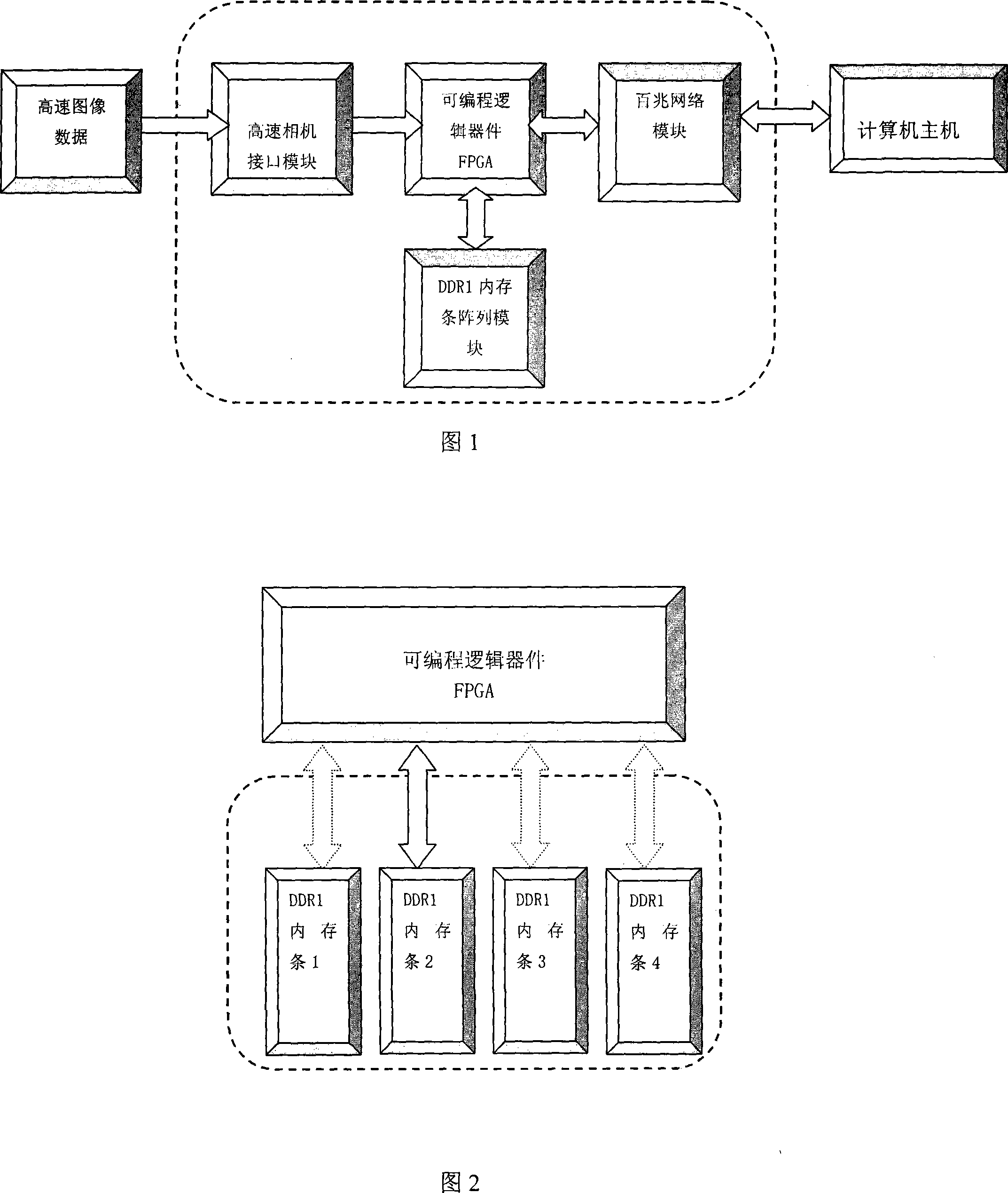
[0017] A recording device involved in a high-speed image recording method based on a memory stick array is composed of a programmable logic device FPGA, a DDR1 memory stick array module, a 100M network module, and a high-speed camera interface module; as shown in the dotted line box in Figure 1 Wherein the DDR1 memory stick array module adopts N DDR1 memory sticks to form a memory stick array module, as a storage medium for high-speed images, here selects a memory stick array module composed of 4 DDR1 memory sticks, as shown in Figure 2;

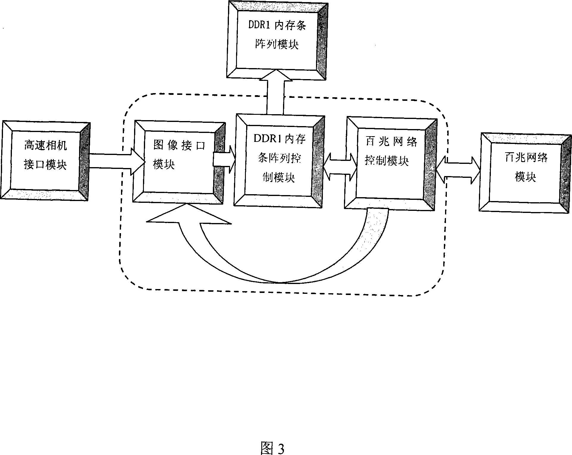
[0018] The programmable logic device FPGA also includes: DDR1 memory array control module, 100M network control module, and image interface module, as shown in Figure 3.

[0019] A high-speed image recording method based on a memory stick array adopts the above-mentioned device, and uses a programmable logi...


PUM


Abstract

The invention provides a recording method of a high-speed image based on a memory bank array, and a recording device using the recording method consists of a programmable logic device FPGA, a 100M network module, a DDR1 memory bank array module and a high-speed camera interface module, wherein, the DDR1 memory bank array module comprises N DDR1 memory banks. The invention is characterized in that: N DDR1 memory banks are controlled to cooperate by the programmable logic device FPGA, image data recording of high speed and high capacity is achieved by using a high speed burst read-write mode, and the 100M network module is used to communicated with a host of a remote computer, thereby achieving the proposal of remote off-line recording; the recording method of the invention used for recording high-speed image data not only can be conveniently operated, but also greatly improves the recording speed, and breaks through the bottleneck of speed of the prior recording proposal.

Description

technical field [0001] The invention relates to a high-speed image data recording method, in particular to a high-speed image recording method based on a memory stick array. Background technique [0002] In some modern high-speed measurement applications, in order to measure the instantaneous high-speed change characteristics of the physical information of the object, it is necessary to use high-speed video acquisition means, such as high-speed CCD, CMOS digital camera for image acquisition, followed by high-speed digital image data flow High-speed digital image acquisition requires high-speed digital image recording equipment as a guarantee. High-speed image recording technology has broad application prospects in automobile crash tests and microscopic biological reaction experiments. [0003] From the perspective of storage media, the current recording media are mainly hard disks, which adopt a mechanical addressing method, which has the disadvantages of low read and write ...

Claims


Application Information

Patent Timeline
Patent Type & Authority Applications(China)
IPC IPC(8): H04N5/77H04N5/765
Inventor 陈强徐启明张启衡彭先蓉
Owner INST OF OPTICS & ELECTRONICS - CHINESE ACAD OF SCI
Learn More