
Electric discharge machining apparatus

A processing device, electric spark technology, applied in electric processing equipment, accessories, metal processing equipment, etc., can solve the problems of increased discharge energy, difficulty in high frequency voltage, high cost, etc., to reduce discharge energy, improve surface The effect of finish

Inactive Publication Date: 2008-07-23
FANUC LTD
View PDF3 Cites 1 Cited by
  • Summary
  • Abstract
  • Description
  • Claims
  • Application Information

AI Technical Summary

Problems solved by technology

[0010] In finishing, in order to improve the surface finish of the machined surface, it is necessary to reduce the discharge energy, but in the cable connecting the voltage measurement circuit (the voltage measurement circuit measures the voltage between the workpiece and the electrode) and the electrodes, etc. The discharge of the existing parasitic capacitance is added to the normal intended discharge, which constitutes the cause of increasing the discharge energy and reducing the surface finish of the processed surface
As a method of reducing the influence of the parasitic capacitance present in the cable of the voltage measurement circuit for measuring the inter-electrode voltage, in principle, the method of using a photocoupler as shown in the above-mentioned Japanese Patent Application Laid-Open No. 7-328844 can be considered, but, It is quite difficult to insulate and transmit the high-frequency voltage during finishing machining with high precision, so even if it can be realized, it will require a very high cost
[0011] In addition, in the method of inserting a resistor into the cable of the inter-electrode voltage measurement circuit to detect the inter-electrode voltage and suppress the discharge of the parasitic capacitance as described in the above-mentioned JP-A-7-328844, there is a difference in the measured inter-electrode voltage. Determining Waveform Weakening Problems
Coaxial cables or shielded wires are generally used in the voltage measurement line for measuring the voltage between the workpiece and the electrode. Such cables have a large inter-line capacitance, so there is a low-pass filter formed by the above-mentioned series resistance and cable capacitance. device, to determine the problem of weakening waveform

Method used


Image

  • Electric discharge machining apparatus
  • Electric discharge machining apparatus
  • Electric discharge machining apparatus

Examples


Embodiment Construction

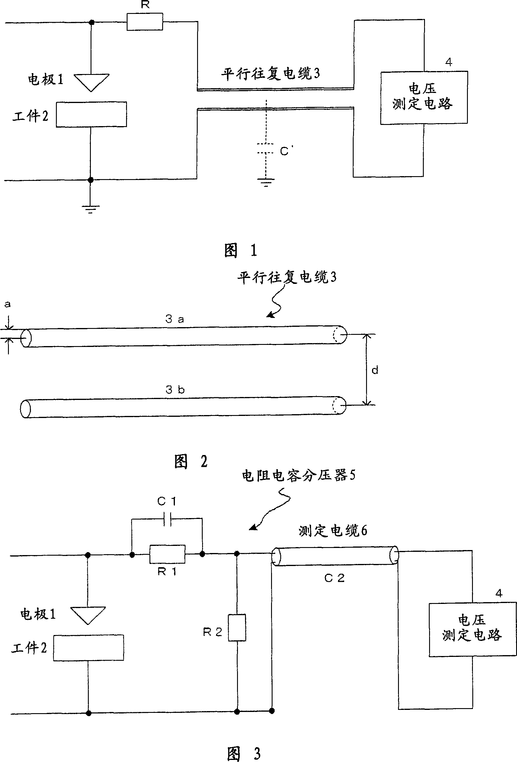
[0028] Fig. 1 is a schematic diagram of main parts of a first embodiment of the present invention. This first embodiment is characterized in that a voltage measurement circuit for measuring the inter-electrode voltage between the electrode and the workpiece is connected using a parallel reciprocating cable having a wide distance between lines, such as a feeder line for a TV antenna.

[0029] In FIG. 1 , reference numeral 1 is an electrode, and reference numeral 2 is a workpiece of a workpiece. A voltage is applied between the electrode 1 and the workpiece 2 (between the electrodes) by a machining power source (not shown). In addition, reference numeral 4 is a voltage measurement circuit for measuring the inter-electrode voltage between the electrode 1 and the workpiece 2, and the discharge state is monitored based on the inter-electrode voltage measured by the voltage measurement circuit 4, and the electrode 1 with respect to the workpiece 2 is monitored. Control of relative ...


PUM


Abstract

The present invention relates to an electric discharge machining apparatus. A voltage measurement circuit (4) is connected between an electrode and a workpiece by a parallel cable through a resistor (R) to measure a machining gap voltage. The parallel cable, like a television antenna feeder line, is formed such that two conductive wires are parallel fixed by an insulating and flexible material such as rubber or resin with a predetermined distance. The interline distance of the parallel cable is increased to decrease a stray capacitance of the cable, so that a high-frequency voltage in finish machining can be measured by the voltage measurement circuit without being attenuated. The resistor (R) is connected to suppress oscillation of a voltage input to the voltage measurement circuit.

Description

technical field [0001] The present invention relates to an electric discharge machining device capable of improving the surface roughness of a machined surface during finishing machining. Background technique [0002] In EDM, a voltage is applied between an electrode in a machining fluid and a workpiece to create an arc discharge. The heat of the discharge is used to melt the workpiece, and at the same time, the machining fluid is heated violently to generate a vaporization explosion and blow away the molten workpiece. Processing is performed by repeating this process at a high frequency. In addition, the small discharge traces formed by discharge form the processed surface, so the size of each discharge trace determines the surface finish. [0003] Because the size of the discharge traces generally depends on the size of each discharge energy, in finishing, in order to improve the surface finish, it is necessary to suppress the single discharge energy to a minimum. [00...

Claims


Application Information

Patent Timeline
Patent Type & Authority Applications(China)
IPC IPC(8): B23H1/02
CPCB23H1/02B23H11/006
Inventor 村井正生樱井章博
Owner FANUC LTD
Learn More