
Photovoltaic power generation tracking controller based on digital signal processor

A maximum power tracking, digital signal technology, applied in photovoltaic power generation, output power conversion devices, optical radiation generators, etc., can solve problems such as limiting the promotion of photovoltaic grid-connected systems, high cost of photovoltaic grid-connected systems, and complex control methods. , to achieve excellent tracking accuracy and stability, reduce the impact of single-branch faults, and reduce costs

Inactive Publication Date: 2008-07-23
TIANJIN UNIVERSITY OF TECHNOLOGY
View PDF0 Cites 38 Cited by
  • Summary
  • Abstract
  • Description
  • Claims
  • Application Information

AI Technical Summary

Problems solved by technology

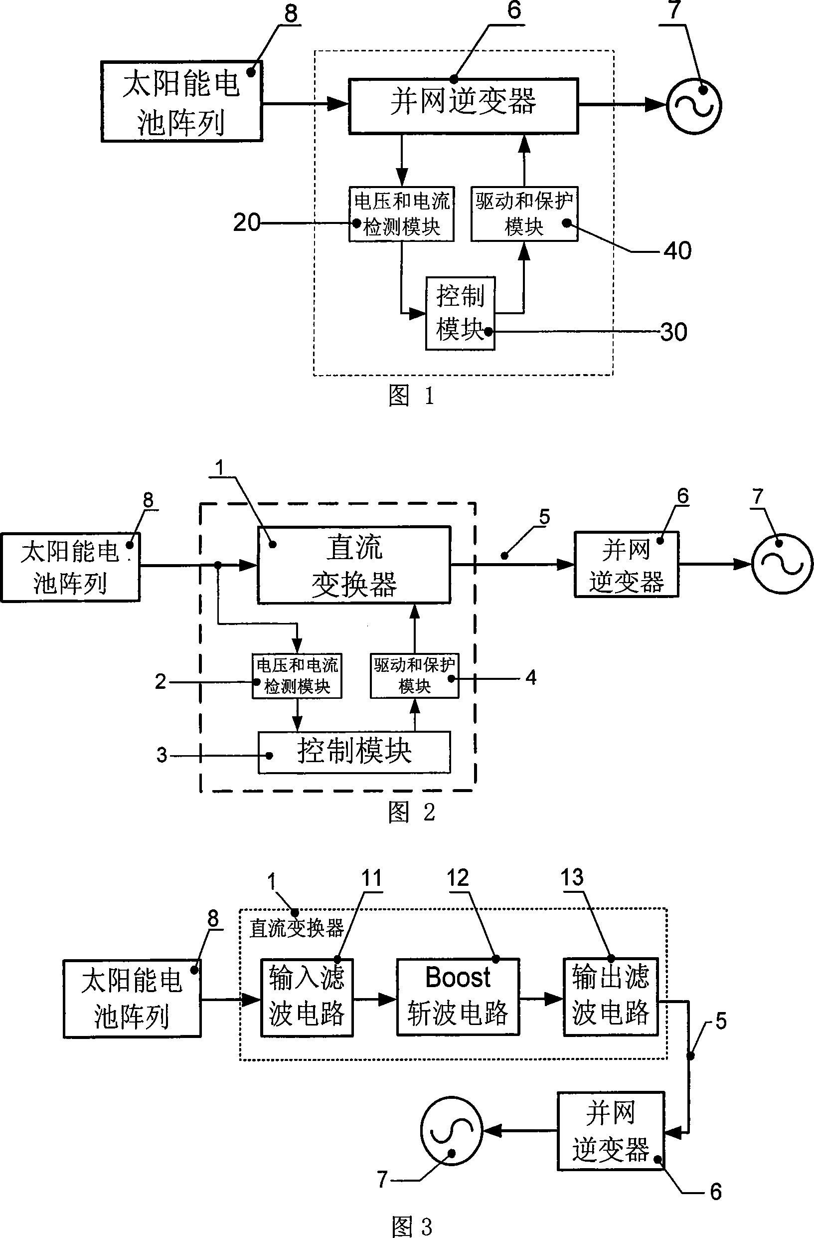
The defect in the above-mentioned prior art is that the grid-connected inverter (60) needs to convert the direct current output by the solar cell array (8) into an alternating current that meets the requirements of the power grid (7), and also has the function of maximum power tracking
Therefore, its control method is extremely complicated and difficult to realize
Since the grid-connected inverter (6) must have an isolation transformer to electrically isolate the photovoltaic grid-connected system from the grid, the cost of the photovoltaic grid-connected system is high, and ordinary users cannot bear it, thus limiting the promotion of photovoltaic grid-connected systems

Method used


Image

  • Photovoltaic power generation tracking controller based on digital signal processor
  • Photovoltaic power generation tracking controller based on digital signal processor
  • Photovoltaic power generation tracking controller based on digital signal processor

Examples


Embodiment Construction

[0034] Embodiments of the present invention will be further described below in conjunction with the accompanying drawings.

[0035] Fig. 2 is a connection block diagram of the photovoltaic power generation maximum power tracking control device of the present invention.

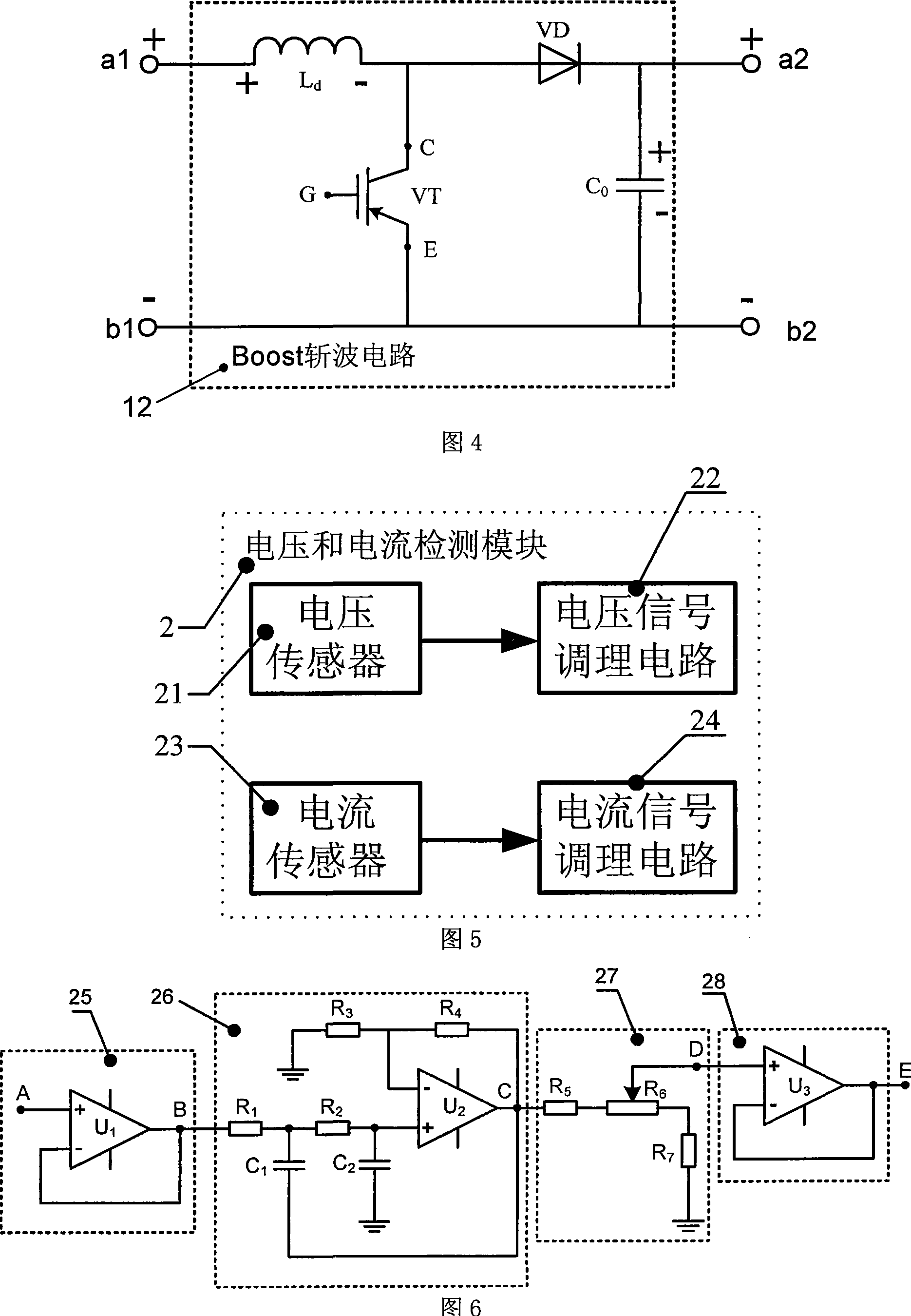
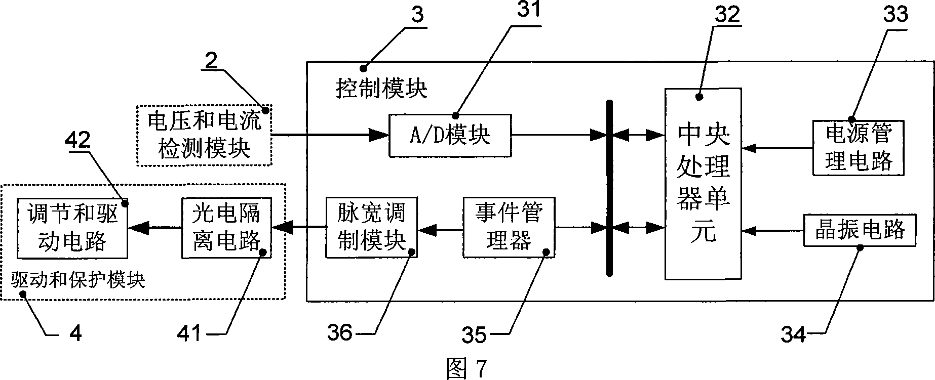
[0036] As shown in Figure 2, the present invention provides a photovoltaic power generation maximum power tracking control device based on a digital signal processor. The photovoltaic power generation maximum power tracking control device based on a digital signal processor includes: a DC converter 1, voltage and current Detection module 2, control module 3, drive and protection module 4; the input end of the DC converter 1 is connected to the output end of the solar battery array 8, and the output end of the DC converter 1 is connected to the grid-connected inverter 6 through the DC bus 5 The input end of the grid-connected inverter 6 is connected to the grid 7; the input end of the voltage and current detect...


PUM


Abstract

The invention discloses a photovoltaic power-generating maximal power tracking controlling device which is on the basis of digital signal processing device, the device comprises a direct current converter, a voltage and electric current detecting module, a controlling module and a driving and protecting module, wherein the input end of the direct current converter is connected with the output end of a solar battery array, the output end is connected with the input end of a grid-connected inverter through a direct current generatrix, the grid-connected inverter is connected with an electric net, the input end of the voltage and electric current detecting module is connected with the output end of the voltage and electric current detecting module, the output end of the voltage and electric current detecting module is connected with the input end of the controlling module, the output end the controlling module is connected with the input end of the driving and protecting module, and the output end of the driving and protecting module is connected with a grid electrode G of a isolated-gate bipolar field effect transistor of the direct current converter. The invention has the advantages of low cost, which is easy to popularize and use, reduces the difficulty of the system controlling realization, and increases controlling effect. The installation of the invention is flexible, maintenance is convenient, and the influence of a single branch road fault can be reduced in maximum limit.

Description

technical field [0001] The invention relates to the technical field of control of solar photovoltaic grid-connected power generation, in particular to a maximum power tracking control device for photovoltaic power generation based on a digital signal processor. Background technique [0002] As an important renewable energy source, solar energy is abundant and clean, and it is an important part of the energy strategy for sustainable development of human beings. It has developed rapidly in recent years. The transformation of solar energy from supplementary energy to alternative energy, the development of solar power from areas without electricity to areas with electricity, and the development of solar photovoltaic systems from off-grid independent photovoltaic systems to photovoltaic grid-connected systems are the three development trends of solar energy utilization. There is a working point at which the solar cell array outputs the maximum power at any moment, which is called...

Claims


Application Information

Patent Timeline
IPC IPC(8): H02J1/10H02M3/315H02N6/00
CPCY02E10/56
Inventor 周雪松郭润睿马幼捷尹向前程德树
Owner TIANJIN UNIVERSITY OF TECHNOLOGY
Learn More