Ethernet transmission method and Ethernet transmitting/receiving device based on coaxial cable network

A transceiver device, coaxial cable technology, applied in the field of Ethernet physical layer transmission, can solve the problems of large transmission attenuation, the receiving end cannot receive signals, and the transmission attenuation affects the correct decoding of the receiving end, etc., and achieves low cost and eliminates signal distortion. Effect

Active Publication Date: 2008-07-23
NEW H3C TECH CO LTD
View PDF0 Cites 2 Cited by
  • Summary
  • Abstract
  • Description
  • Claims
  • Application Information

AI Technical Summary

Problems solved by technology

[0016] Change the transmission medium from twisted pair to coaxial cable, and if the transmission level of the transceiver device of the Ethernet signal access point does not change, if the transmission end of the access point and the transceiver device of the coaxial terminal follow the The IEEE 802.3 standard sends voltage to send signals, and the receiving end also receives signals according to the standard receiving reference level. Due to the branch equipment in the coaxial distribution network, the transmission between the access point and the coaxial terminal and between the coaxial terminals is attenuated Larger, because the transmission attenuation affects the correct decoding of the receiving end, so that the receiving end cannot receive the signal transmitted through the coaxial distribution network

Method used


Image

  • Ethernet transmission method and Ethernet transmitting/receiving device based on coaxial cable network
  • Ethernet transmission method and Ethernet transmitting/receiving device based on coaxial cable network
  • Ethernet transmission method and Ethernet transmitting/receiving device based on coaxial cable network

Examples


Embodiment 1

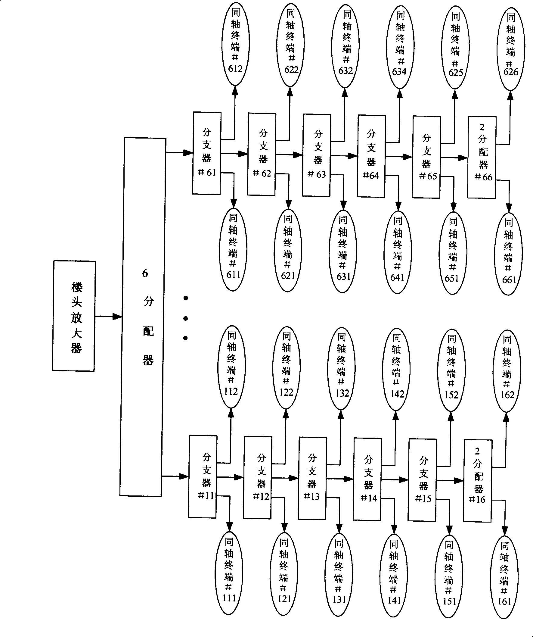
[0050] see Figure 5 , Figure 5 It is a structural schematic diagram of a physical layer chip of an Ethernet transceiver device supporting Ethernet transmission on a coaxial cable network in the present invention. The Ethernet transceiver is suitable for the Ethernet access point and each coaxial terminal in the coaxial cable distribution network. and Figure 4 Similar in structure, the physical layer chip in the transceiver device includes an analog interface 110, an AD / DA (analog-to-digital / digital-to-analog) unit 120, a codec unit 130, and a MAC layer interface unit 140, and Figure 4 and Figure 5 The functions of the above modules are also the same.

[0051] and Figure 4 The difference in is that Figure 5 The function of the AD / DA (analog-to-digital / digital-to-analog) unit 120 in the physical layer chip of the shown transceiver device is divided into a receiving analog / digital conversion unit 240 and a sending digital / analog conversion unit 280; in the sending di...

Embodiment 2

[0068] The second embodiment provided by the present invention is as Figure 6 As shown, the second embodiment is an optimized embodiment of the physical layer chip structure of the transceiver device. The difference between the second embodiment and the physical layer chip structure of the transceiver device of the first embodiment is that:

[0069] (1) The physical layer chip of the transceiver device, in the receiving direction, is also connected with an intersymbol interference canceling unit 250 after receiving the analog / digital conversion unit 240, and the intersymbol interference canceling unit 250 is used for rejecting the received signal after the analog to digital conversion The crosstalk signal in .

[0070] (2) The physical layer chip of the transceiver device, in the sending direction, also includes a sending pre-emphasis unit 270 and a sending digital / analog conversion unit 280, and the sending pre-emphasis unit 270 is connected in series with the voltage amplif...


PUM


Abstract

The invention relates to an ethernet tranceiving device on the basis of a coaxial cable network and a method for transmitting the Ethernet, the receiving device comprises an analog interface (110) which is connected with a coaxial cable, a voltage amplification unit (260) which is connected with the analog interface (110) and used to amplify sent signal electric levels of the analog interface (110), a receiving unit (200) which is connected with the analog interface (110), wherein the receiving unit (200) comprises a receiving and amplifying unit (210) which is used to amplify received signal electric levels form the analog interface (110), wherein the magnification factors of the voltage amplification unit (260) and the receiving and amplifying unit (210) are confirmed by attenuation characteristics parameters of a coaxial cable distributing network. The method for transmitting comprises: amplifying service signals before sending services and amplifying the service signals on the direction of receiving the services. The invention can realize that baseband electrical signals of the ethernet are transmitted in a coaxial distributing network and the cost is low.

Description

technical field [0001] The present invention relates to Ethernet physical layer transmission technology, in particular to an Ethernet transceiver device and an Ethernet transmission method based on a coaxial cable network; specifically, to an Ethernet transceiver device based on a cable television coaxial cable distribution network, and The physical layer transmission method of Ethernet over coaxial cable distribution network. Background technique [0002] In the existing cable TV fiber coaxial network (HFC), the TV program is transmitted from the front end to the optical node of the TV network close to the user through the optical fiber (generally, an optical node covers 300 to 500 users in the surrounding area). After the optical signal is converted into an electrical signal at the node, the TV signal is transmitted to each resident's home through the residential building through the coaxial cable distribution network. As people's demand for two-way transmission of new se...

Claims


Application Information

Patent Timeline
IPC IPC(8): H04L12/02H04L12/28H04B3/00
Inventor 于洋
Owner NEW H3C TECH CO LTD
Why Eureka
Try Eureka