Drill bit

A drill bit and cutting edge technology, which is applied in the direction of drill repair, drill tool accessories, drilling/drilling equipment, etc., can solve the problems of drill bit breakage, tool life reduction, and insufficient chip countermeasures, so as to prevent breakage and improve rigidity , The effect of prolonging the life of the drill bit

Inactive Publication Date: 2008-07-23
OSG
View PDF1 Cites 5 Cited by
  • Summary
  • Abstract
  • Description
  • Claims
  • Application Information

AI Technical Summary

Problems solved by technology

[0009] However, in the above-mentioned drills, the countermeasures for chip discharge are insufficient.
Therefore, there is a problem that the drill bit is broken due to the clogging of chips, and the tool life is reduced.

Method used


Image

  • Drill bit
  • Drill bit
  • Drill bit

Examples


Embodiment Construction

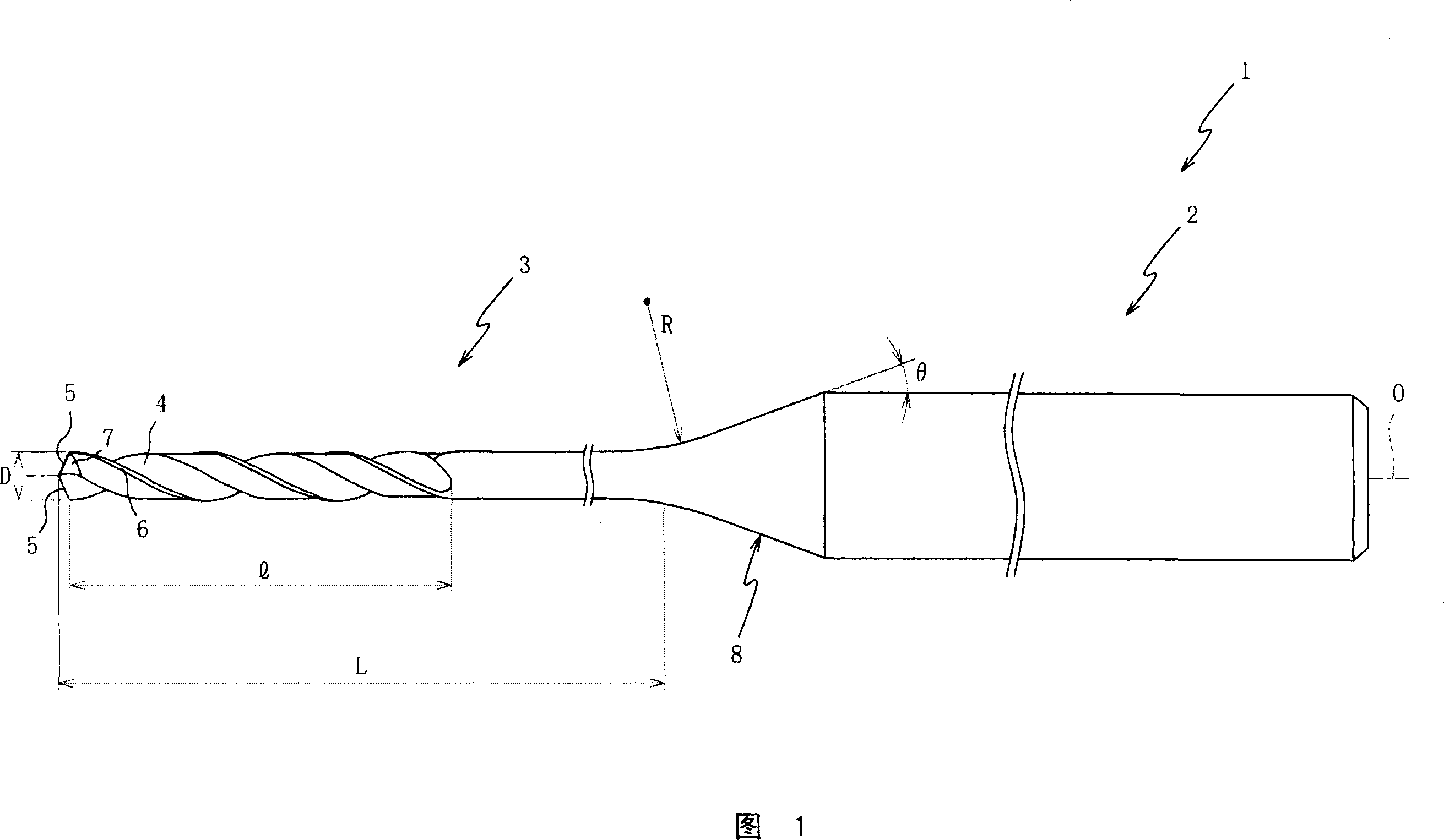
[0051] Hereinafter, preferred embodiments of the present invention will be described with reference to the drawings. Fig. 1 is a front view showing a drill 1 according to an embodiment of the present invention. In addition, in FIG. 1, illustration of the axial length of the drill shank 2 and the drill body 3 is omitted.

[0052] The drill bit 1 is a small-diameter cutting tool, which utilizes the rotational force transmitted from a processing machine (drilling machine, etc.), and is mainly used to pierce the initial hole as a through hole for the metal wire during wire cutting, as shown in Figure 1. It mainly has a drill shank 2 held on the above-mentioned processing machine and a drill body 3 for cutting the material to be cut.

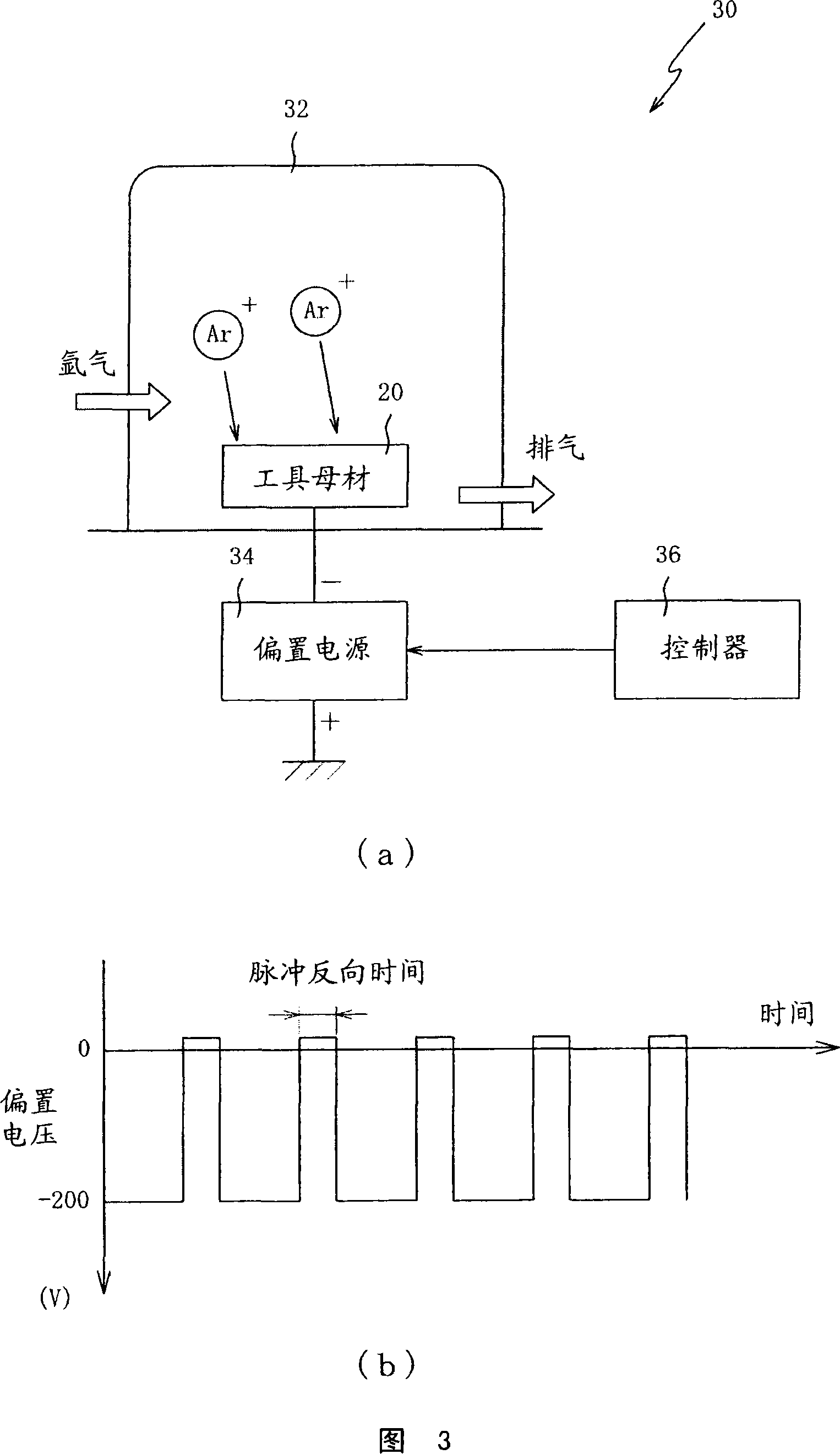
[0053] In addition, the drill bit 1 has a coating film of TiAlN as a hard compound formed on the surface by a sputtering method described later, and the thickness of the TiAlN is set to be within a range of 1.0 μm or less. In addition, the details will b...


PUM


Abstract

To provide a drill enabling an increase in tool life while securing working efficiency. In this drill (1), a groove length (l) is set within the range of 6D to 10D where the outer diameter of the cutting edges (5) is D, the coating dimension of a hard compound on the surfaces of at least cutting edges (5) is set to 1.0 [mu]m or less, and the number of the cutting edges (5) is set to two. Since the chip discharging property and the rigidity of the drill can be synergistically increased, the lifetime of the drill (1) can be synergistically increased.

Description

Technical field [0001] The invention relates to a drill bit, in particular to a drill bit that can ensure processing efficiency and prolong the life of the tool. Background technique [0002] Generally speaking, wire-cutting processing refers to processing that is performed by causing an electric current to flow through a metal wire mainly made of brass and using the generated electric discharge. During the processing, it is necessary to pierce the material to be cut with an initial hole as a through hole for the metal wire. For the material to be cut with particularly high hardness, the initial hole is pierced by electrical discharge machining. [0003] However, in the electrical discharge machining, the machining efficiency is significantly reduced, and accordingly, there is a problem that the machining efficiency of the wire cutting machining as a whole is reduced. [0004] In addition, when performing high-precision hole machining with a φ0.5mmH7 tolerance on high-hardness ma...

Claims


Application Information

Patent Timeline
Patent Type & Authority Applications(China)
IPC IPC(8): B23B51/00
Inventor 桝田典宏
Owner OSG
Why Eureka
Try Eureka