Underwater communications system

An underwater communication and magnetic signal technology, applied in the transmission system, electrical components, etc., can solve the problems of propagation wave attenuation, conduction loss, etc., achieve low carrier frequency, low attenuation, and reduce the difficulty of communication

Inactive Publication Date: 2008-07-23
WIRELESS FIBER SYST
View PDF3 Cites 32 Cited by
  • Summary
  • Abstract
  • Description
  • Claims
  • Application Information

AI Technical Summary

Problems solved by technology

However, in order to propagate electromagnetic waves, energy is constantly cycled between magnetic and electric fields, and due to conduction losses, this leads to attenuation of the propagating waves
[0006] Attenuation losses, bandwidth limitations, and the limited distances over which data can be transmitted all present significant practical problems for underwater communications

Method used


Image

  • Underwater communications system
  • Underwater communications system
  • Underwater communications system

Examples


Embodiment Construction

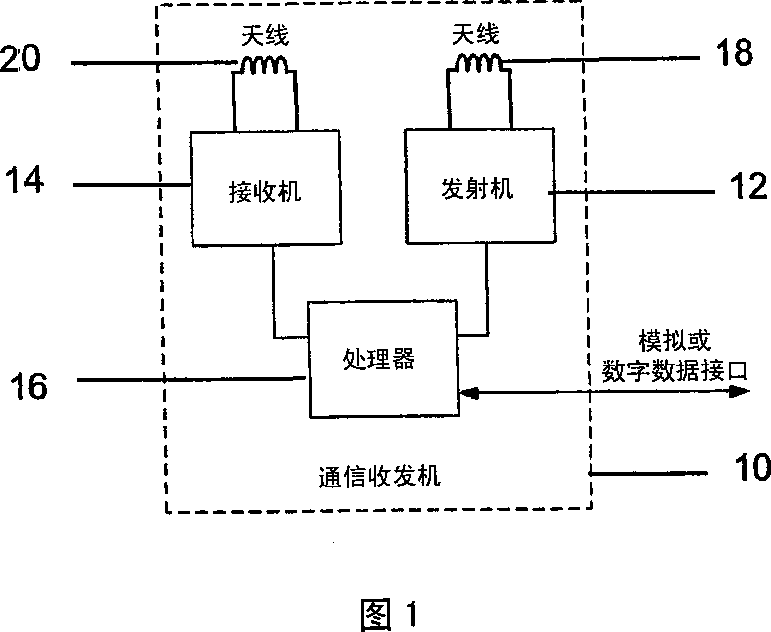
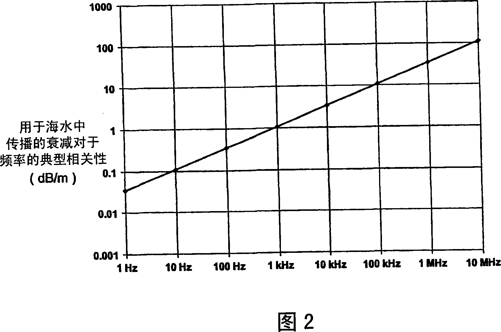
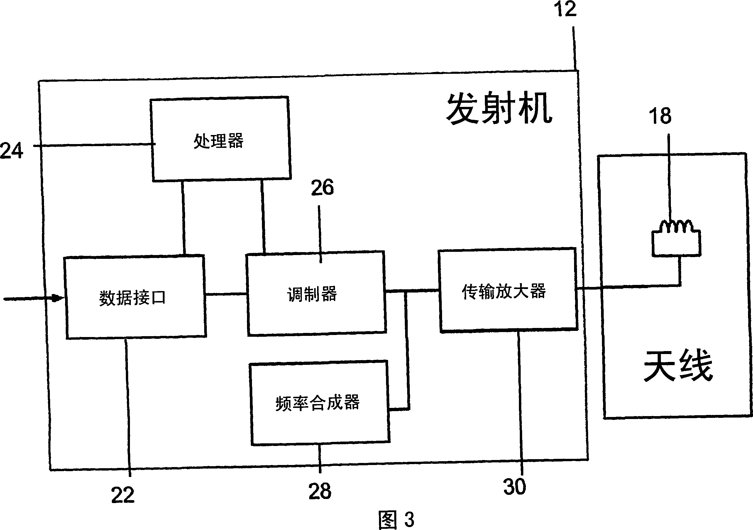
[0037] The present invention relates to various underwater communication systems using electromagnetic waves as the propagation mode. Each of these communication systems uses a communication transceiver 10 having a transmitter 12, a receiver 14, and a processor 16 (shown in FIG. 1) connected to an analog or digital data interface (not shown). The transmitter and receiver 12 and 14 have waterproof, electrically insulated magnetic coupling antennas 18 and 20, respectively. Alternatively, a single antenna can be shared between the transmitter and receiver. Magnetic coupling antennas are used because water is a conductive medium, so magnetic coupling antennas have a significant impact on the propagation of electromagnetic signals. Ideally, each insulated antenna assembly is surrounded by a low-conductivity medium (such as distilled water) that matches the impedance of the propagation medium.

[0038]In the communication system embodying this invention, an electrically insulated magnet...


PUM


Abstract

An underwater communications system for transmitting electromagnetic and/or magnetic signals to a remote receiver, the system having a data input; a digital data compressor for compressing data that is to be transmitted; a modulator for modulating the compressed data onto a carrier signal and an electrically insulated, magnetic coupled antenna for transmitting the compressed, modulated signals.

Description

Technical field [0001] The invention relates to an underwater communication system, which uses electromagnetic propagation and magnetic induction as transmission methods and optimizes the distance that can be reached by digital transmission of information. Background technique [0002] Various underwater communication systems are known. One of the most common is based on acoustic technology. The problem with this system is that noise and interference from multiple sources deteriorate the performance of the system. They are also affected by multipath effects and are essentially unusable in some environments. Other underwater communication systems use radio links (such as very low frequency electromagnetic signals), which are usually used for long-distance communication between surface stations and underwater ships. Typically, these systems use physically large electric field coupled antennas to operate in the far field and support data rates of up to several bits per second. [00...

Claims


Application Information

Patent Timeline
Patent Type & Authority Applications(China)
IPC IPC(8): H04B13/02
CPCH04B13/02
Inventor 马克·罗德斯布兰登·海蓝德里克·沃尔夫
Owner WIRELESS FIBER SYST
Why Eureka
Try Eureka