Pile machine having drilling function and drilling static pressure method

A drilling method and pile driver technology, which is applied to drilling equipment and methods, rotary drilling rigs, drill pipes, etc., and can solve problems such as pressure explosion of pipe piles and destructive cracks in buildings

Active Publication Date: 2008-07-30
浙江兆弟技术有限公司
View PDF0 Cites 6 Cited by
  • Summary
  • Abstract
  • Description
  • Claims
  • Application Information

AI Technical Summary

Problems solved by technology

Its shortcomings: Although the static pressure pile machine has the function of forcing the static pressure pile, due to the different geological structures underground, for the structure of the dense ground, it will be tens of meters long with a diameter of tens of centimeters to one meter. The pipe piles are forced to be pressed into the ground. First, it is easy to cause the pipe piles to be overstressed and explode; second, the extruded underground soil is forced to move under the extrusion of the pipe piles, which is easy to cause destructive cracks in the surrounding buildings, etc. damage

Method used


Image

  • Pile machine having drilling function and drilling static pressure method

Examples


Embodiment 1

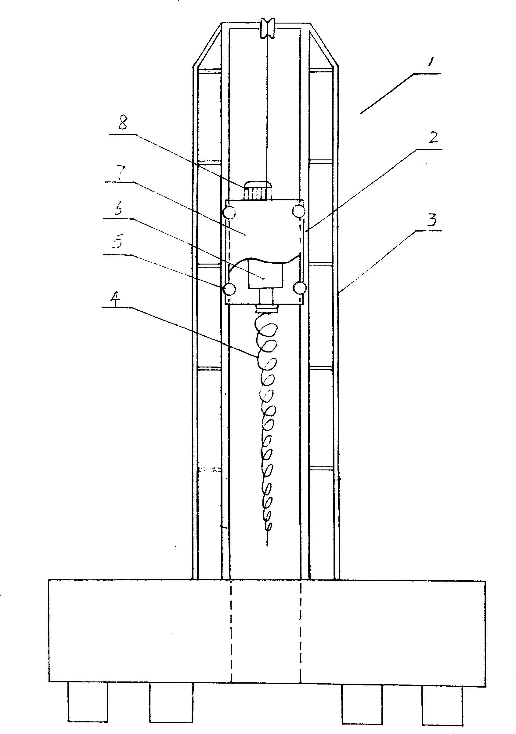
[0009] Embodiment 1: with reference to attached figure 1 . A pile driver with a drilling function, which includes a static pressure pipe pile machine 1, a drilling device 2 is located between the vertical frames of the static pressure pipe pile machine and is connected to the traction mechanism on the top of the static pressure pipe pile machine frame by a traction rope , move up and down along the vertical frame under the traction of the traction mechanism, that is to say, the guide pulley in the drilling device 2 is located between the vertical frame rails 3 in the static pressure pipe pile machine, and the drilling device 2 is connected to the vertical frame by the traction rope The traction mechanism on the top of the static pressure pipe pile machine frame is connected and moves up and down along the vertical frame rail 3 under the traction of the traction mechanism. Erection frame rail 3 is I-shaped steel track or channel steel track or angle steel track. Drilling devi...

Embodiment 2

[0010] Embodiment 2: On the basis of Embodiment 1, the drilling method of the static pressure pipe pile machine with drilling function, the guide pulley in the drilling device (the guide pulley is a groove structure) is stuck in the static pressure pipe pile machine Between the vertical frame rails in the static pressure pipe pile machine, the traction mechanism located at the top of the static pressure pipe pile machine frame drives the drilling device to move down along the vertical frame frame rails in the static pressure pipe pile machine through the traction rope (wire rope, etc.), Make the drill bit contact with the ground to be drilled, then start the power machine, the power machine drives the drill bit to drill, the soil drilled by the drill bit is automatically transported to the ground along the spiral soil extraction drill, when the drilling device is under the action of its gravity, the drill bit When the required depth is reached, the drill bit device stops workin...


PUM


Abstract

The invention relates to a device and a method which make use of a static pile press machine for drilling and piling, and the device comprises the static pile press machine and a drilling system that is positioned among upright standers in the static pile press machine and is connected with a draughting mechanism on the top of the stander of the static pile press machine by a pulling rope; the drilling system moves up and down along the upright standers under the traction of the draughting mechanism. The invention has the advantages of initiating the precedent that a static tube pile machine is provided with the drilling system, leading the static tube pile machine not only to have the function of static tube pile, but also to have the function of drilling, and solving the phenomenon of press bursting caused by excessive stress of a tube pile by enforcing to static press the tube pile ever since a long time ago. What is more, the damage of destructive crack, etc. occurring in the surrounding building caused by the pressed tube pile is solved.

Description

technical field [0001] The invention relates to a device and method for drilling and pressing piles by using a static pile driver or a pile driver, and belongs to the field of static pile driver or pile driver equipment manufacturing. Background technique [0002] Existing static pressure pipe pile machine, in structural design, by machine platform, erect frame, be positioned at the power traction device and static pressure device of frame frame top. The general static pressure is in the range of 600 tons to 800 tons, and the pipe pile can be statically pressed to the set ground (forming a pile foundation). Its shortcomings: Although the static pressure pile machine has the function of forcing the static pressure pile, due to the different geological structures underground, for the structure of the dense ground, it will be tens of meters long with a diameter of tens of centimeters to one meter. The pipe piles are forced to be pressed into the ground. First, it is easy to ca...

Claims


Application Information

Patent Timeline
Patent Type & Authority Applications(China)
IPC IPC(8): E02D7/00E02D7/20E21B3/02E21B15/00E21B17/22
Inventor 周兆弟
Owner 浙江兆弟技术有限公司
Why Eureka
Try Eureka