
Light spectrum reshaping modulating method for chirp pulse amplification

一种光谱调制、啁啾脉冲的技术,应用在工程光学应用领域,能够解决系统不适用、钕玻璃系统等窄带系统不适用等问题

Inactive Publication Date: 2008-07-30
SICHUAN UNIV
View PDF4 Cites 22 Cited by
  • Summary
  • Abstract
  • Description
  • Claims
  • Application Information

AI Technical Summary

Problems solved by technology

The invention overcomes the problem that the conventional international spectral modulation method is either inapplicable to systems exceeding the terawatt level, or is inapplicable to narrow-band systems such as neodymium glass systems; the method of the present invention can realize spectral modulation and spectral shaping for general laser pulses , especially suitable for spectral modulation and spectral shaping of chirped pulse amplification of large-aperture, high-energy, and high-power lasers with a bandwidth of several nanometers

Method used


Image

  • Light spectrum reshaping modulating method for chirp pulse amplification
  • Light spectrum reshaping modulating method for chirp pulse amplification
  • Light spectrum reshaping modulating method for chirp pulse amplification

Examples


Embodiment 1

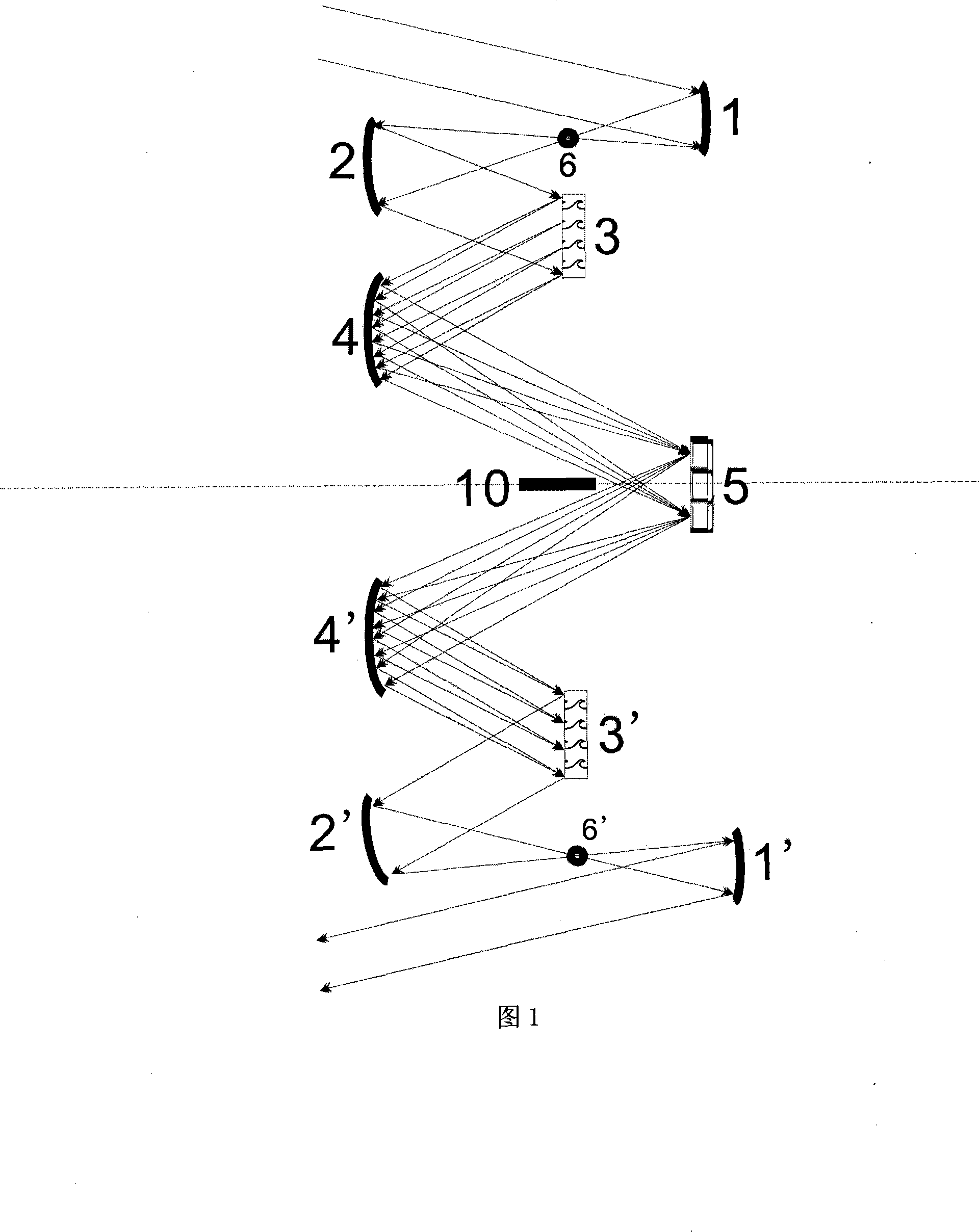
[0107] In this embodiment, the first grating 3 and the second grating 3' are reflective directional planar blazed gratings that can work under large-diameter and high-energy conditions; the planar spectrum modulation reflector is a planar spectrum modulation of a multi-layer dielectric film micro-relief structure Mirrors; all concave mirrors must strictly eliminate chromatic aberration, spherical aberration, and coma, so that the maximum deviation of the spectral image plane from the surface of the plane spectral modulation mirror is less than the half focal depth tolerance derived from the Rayleigh criterion; the first aperture 6 and the third diaphragm 6' are aperture diaphragms, and the second diaphragm 10 is a slit diaphragm formed by the light blocking plate and its image in the plane spectral modulation reflector 5; the first diaphragm 6 is an incident diaphragm, The second aperture 10 is an intermediate aperture, and the third aperture 6' is an exit aperture.

[0108] A...

Embodiment 2

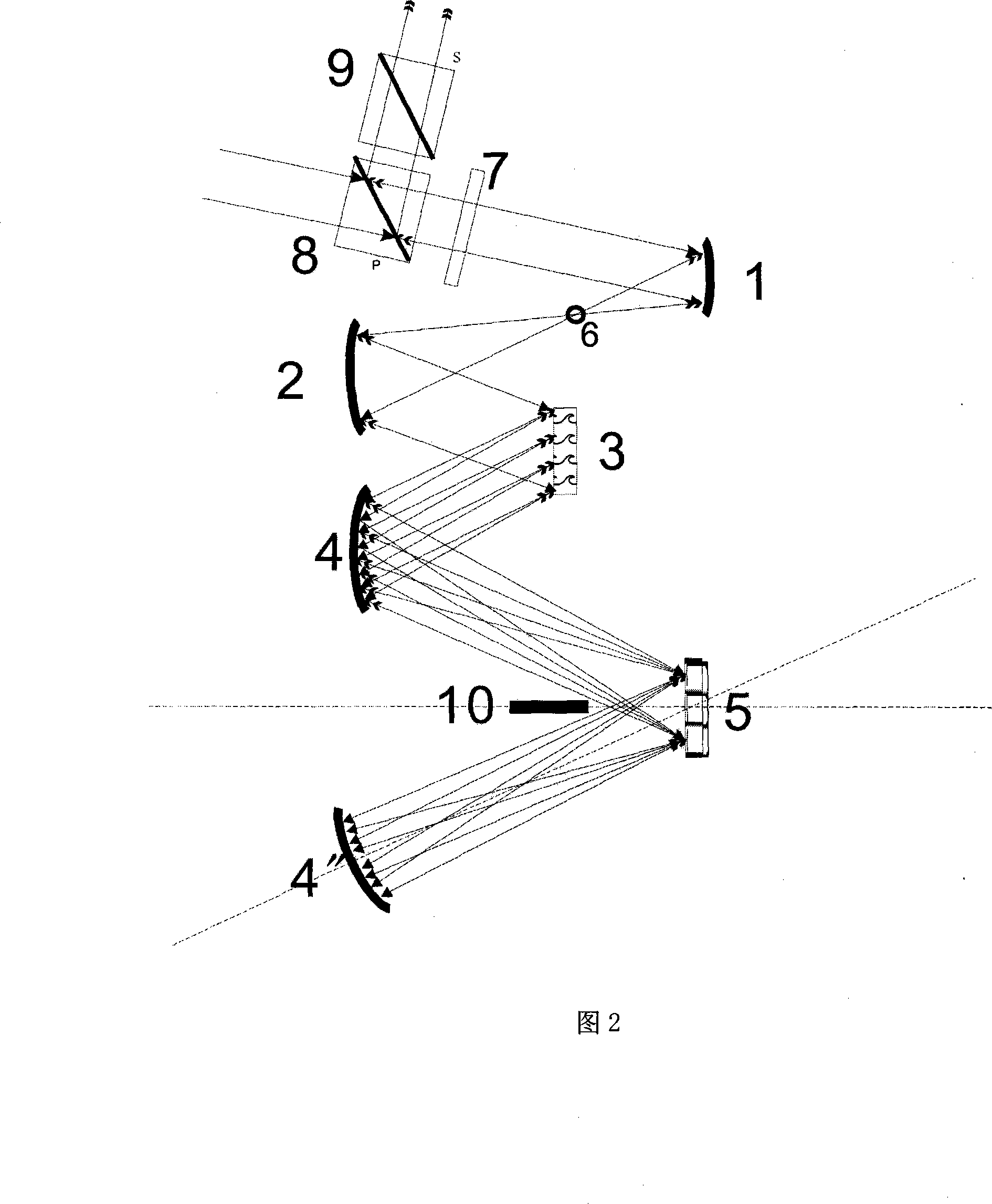
[0116] In this embodiment, the first grating 3 is a reflective directional planar blazed grating that can work under large-aperture and high-energy conditions; the spectrum modulation mirror is a plane spectrum modulation mirror with a multi-layer dielectric film micro-relief structure; all concave mirrors It is necessary to strictly eliminate chromatic aberration, spherical aberration, and coma aberration, so that the maximum deviation of the spectral image plane from the surface of the plane spectral modulation mirror is less than the half focal depth tolerance derived from the Rayleigh criterion; the first stop 6 is the aperture stop, and the second stop Two diaphragms 10 are the slit diaphragms formed by the light blocking plate and its image in the plane spectrum modulation reflector 5; the first diaphragm 6 is the incident diaphragm, the second diaphragm 10 is the middle diaphragm, and the first diaphragm 6 The entrance aperture is also the exit aperture.

[0117] Arrang...

Embodiment 3

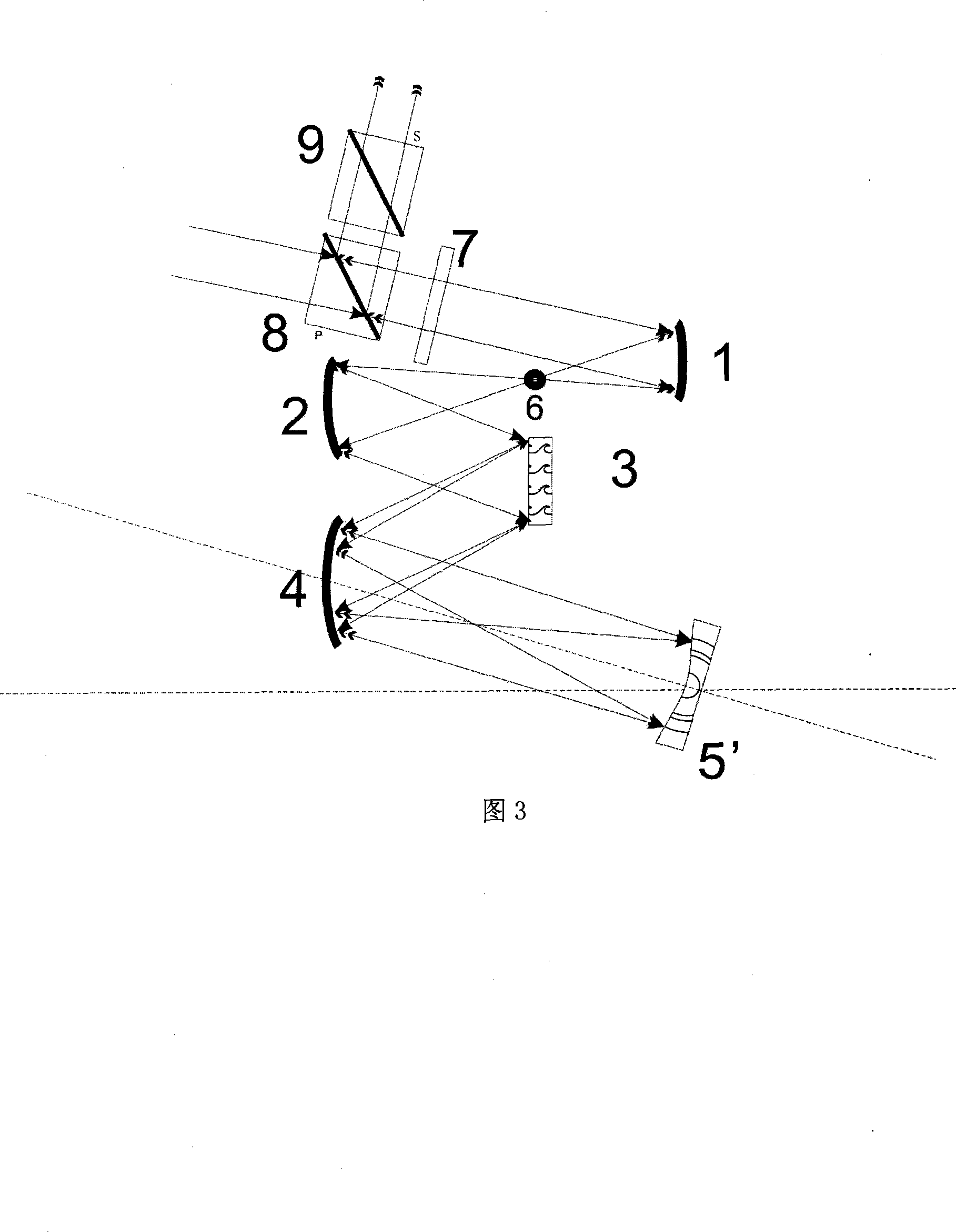
[0124] In this embodiment, the first grating 3 is a reflective directional planar blazed grating that can work under large-diameter and high-energy conditions; the spectrum modulation mirror is a concave spectrum modulation mirror with a multi-layer dielectric film micro-relief structure; the concave mirror used It is necessary to strictly eliminate chromatic aberration, spherical aberration, and coma aberration, so that the maximum deviation of the spectral image plane from the surface of the concave spectral modulation mirror is less than the half focal depth tolerance derived according to the Rayleigh criterion; the first stop 6 is the aperture stop, and the same Also the entrance aperture and the exit aperture.

[0125] Arrange the optical components according to the optical path diagram of the self-collimating concave spectrum modulation CTSI system spectrum shaping modulation structure shown in Figure 3:

[0126] This example is a CTSI spectral decomposition system and a...


PUM


Abstract

The invention relates to a spectral reshaping / modulation method used for a chirped pulse amplification (CPA) system. During the spectral reshaping / modulation process, the method employs a CTSI system consisting of a CTSI spectral decomposition system and a CTSI spectral composition system, wherein, the two systems are symmetrical to each other, and employs a spectral modulation system. The CTSI spectral decomposition subsystem realizes the complete and actual development of laser chirped pulses onto a spectral plane; the spectral modulation subsystem performs the spectral modulation on an image plane; then the CTSI spectral composition subsystem restores the modulated spectra to modulated chirped pulses without distortions, thereby realizing the spectral modulation and reshaping of chirped pulses. The inventive method can realize the spectral modulation and reshaping of common laser pulses, and is particularly suitable for the spectral modulation and reshaping of large-aperture high-power CPA system with band width of several nanometers.

Description

technical field [0001] The invention relates to a pulse shaping modulation technology used in the process of laser power amplification, in particular to a new spectral shaping modulation method suitable for large-aperture, high-energy, high-power chirped pulse amplification (CPA) systems, which belongs to engineering optics application technology field. Background technique [0002] In the ultra-short ultra-intense high-power laser technology, many factors limit the further improvement of the output power of the laser system, among which the gain narrowing and gain saturation effects of the solid-state laser medium are a more difficult problem. The gain narrowing effect is due to the limited width of the atomic emission line of the amplifying medium. Due to the frequency pulling effect, the spectrum of the output pulse is narrowed, which will not only cause the distortion of the pulse waveform, but also make it difficult for the pulse to return to its original width. . The...

Claims


Application Information

Patent Timeline
Patent Type & Authority Applications(China)
IPC IPC(8): G02B17/06G02B27/09H01S3/10
CPCG02B17/0668G02B27/0927G01J2003/1213G02B19/0052H01S3/005G01J2003/1282G02B27/0944G01J3/18G02B19/0023G02B27/0983G01J9/00
Inventor 李铭张彬戴亚平王韬
Owner SICHUAN UNIV
Learn More