
A plurality of stimulating coil transcranial magnetic field stimulator

A technology of stimulators and coils, applied in the field of new transcranial magnetic field stimulators, which can solve the problems of large power consumption of magnetic field stimulators, electromagnetic interference of electrical grid electronic equipment, and difficult synchronization of multiple stimulators, so as to increase the application range, Effect of increasing stimulation pattern and stimulation frequency

Inactive Publication Date: 2008-08-06
WUHAN YIRUIDE MEDICAL EQUIP
View PDF0 Cites 56 Cited by
  • Summary
  • Abstract
  • Description
  • Claims
  • Application Information

AI Technical Summary

Problems solved by technology

[0004] To achieve simultaneous stimulation of multiple parts, it is currently necessary to purchase multiple magnetic field stimulators to work at the same time. Even so, it is difficult for multiple magnetic field stimulators to be synchronized and programmed to work, and the power consumption of multiple magnetic field stimulators is large (the peak power of each More than 3000 watts), the general hospital power supply is unbearable, and it has great electromagnetic interference to the power grid and surrounding electronic equipment

Method used


Image

  • A plurality of stimulating coil transcranial magnetic field stimulator
  • A plurality of stimulating coil transcranial magnetic field stimulator
  • A plurality of stimulating coil transcranial magnetic field stimulator

Examples


Embodiment Construction

[0021] The present invention will be further described below in conjunction with the drawings and embodiments.

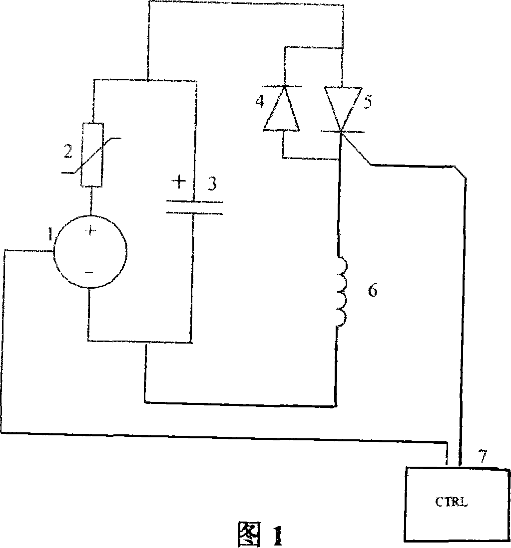
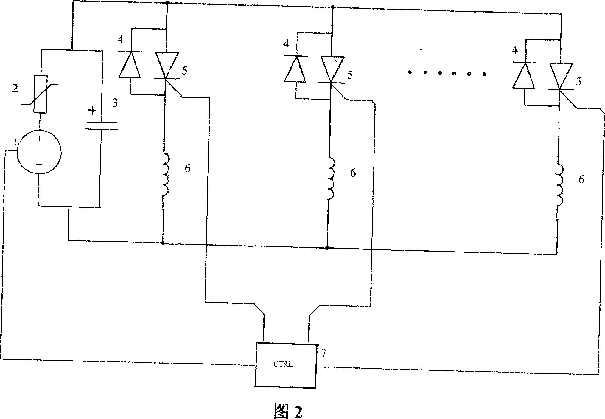
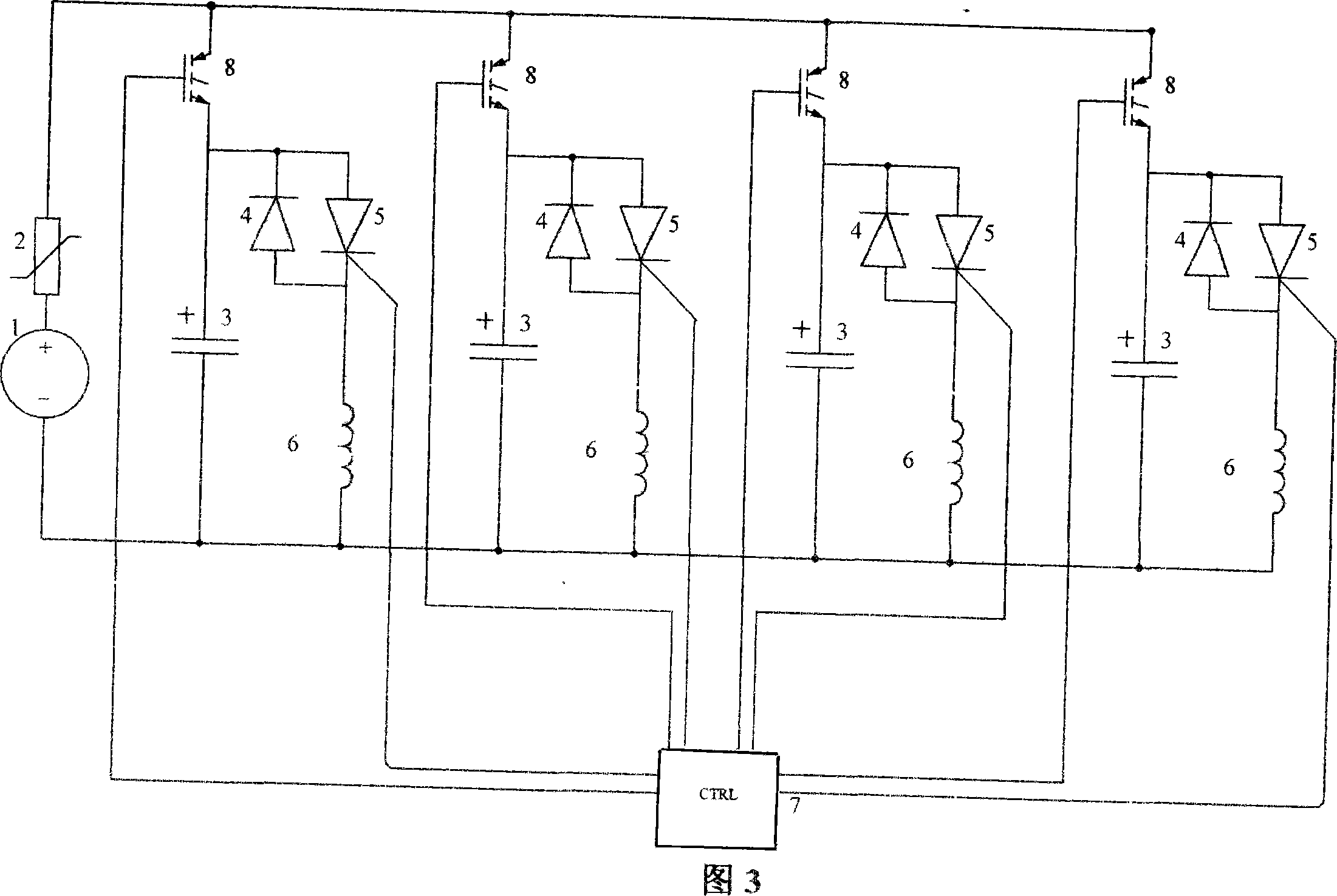
[0022] Explanation marked in the picture: 1- high voltage charging power supply, 2- current limiting resistor, 3- energy storage capacitor, 4- reverse freewheeling diode, 5- thyristor switch, 6-stimulation coil, 7-microcomputer controller, 8-High voltage semiconductor switch.

[0023] Figure 1 is a typical circuit diagram of a prior art magnetic field stimulator with a stimulation coil. The high-voltage charging power supply 1 is connected to the charging current-limiting resistor 2, and the energy storage capacitor 3 is connected in parallel to form a complete high-voltage energy storage circuit. The anode of the capacitor is connected to the anode of the thyristor switch 5 and the freewheeling diode 4, and then connected to the magnetic field stimulation coil 6, forming a series loop back to the cathode of the energy storage capacitor 3. The microcomputer controller 7...


PUM


Abstract

The invention relates to a transcranial magnetic field stimulator with a plurality of stimulating coils which comprises a high voltage charging power supply, a current-limiting resistance, an energy dumped capacitor, a reverse current reflowing diode, a thyristor switch, stimulating coils and a microcomputer controller. The stimulator is characterized in that: a stimulating unit comprises a thyristor switch, a stimulating coil and an energy dumped capacitor; N parallel connected stimulating units are connected to the current-limiting resistance and the high voltage charging power supply end; N stimulating units shared use an energy dumped capacitor; the microcomputer controller ends are respectively connected with the triggering ends of the thyristor switch in every stimulating unit; N is more than or equal to 2. A magnetic field stimulator of the invention can substitute a plurality of magnetic field stimulators in using, realizes the in-turn stimulation of a plurality of stimulating coils, and ensures a plurality of parts to get continuous stimulation from the program control. If the number of the energy dumped capacitor is increased, a plurality of coils not only can be stimulated in time sharing, but also achieving synchronous stimulation and couple stimulation.

Description

Technical field [0001] The invention relates to a new type of transcranial magnetic field stimulator, a single transcranial magnetic field stimulator with multiple stimulation coils, and the output parameters of each stimulation coil are controlled by a computer program. Background technique [0002] Beginning in 1985, Dr. BARKER in the United Kingdom used pulsed magnetic fields to stimulate the cerebral cortex to induce motor evoked potentials in the hands. Transcranial magnetic field stimulation technology has been developed and popularized for more than 20 years. Magnetic field stimulation is a non-destructive, painless, non-contact, non-invasive technique to stimulate the central and peripheral nerves of the brain. It is widely used in neuroscience research, clinical medicine diagnosis, treatment and rehabilitation. The magnetic field stimulator is based on the Faraday electromagnetic induction principle. It uses DC high voltage to charge the energy storage capacitor, and use...

Claims


Application Information

Patent Timeline
IPC IPC(8): A61N2/02A61N2/04
Inventor 孙逸华廖家华余维新陈丹
Owner WUHAN YIRUIDE MEDICAL EQUIP
Learn More