Three-layer type sleeping cabin

A technology of sleeping cabin and bottom layer, which is applied in the direction of living cabins, sleeper appliances, transport passenger cars, etc. It can solve the problems of complex movements, high difficulty in moving the bed, and inability to provide comfortable sitting environment for passengers.

Inactive Publication Date: 2008-08-06
于君
View PDF1 Cites 10 Cited by
  • Summary
  • Abstract
  • Description
  • Claims
  • Application Information

AI Technical Summary

Problems solved by technology

[0004] 1. The height of the upper and middle berths from the floor of the carriage is too high, it is difficult for passengers to get on and off the berths, the movements are complicated, inconvenient, and not safe enough
In particular, it is more difficult to climb on the upper bunk that is more than 2.2 meters above the floor
[0005] 2. The bunk space on each floor is open, and cannot provide independent and closed bedroom space for each passenger, lacking privacy and security
[0006] 3. The upper and middle berths do not provide passengers with the floor space for standing or resting their feet similar to those of the lower berths. Therefore, if the passengers on the upper and middle berths want to stand up, they have to climb down the stairs before they can stand. On the floor of the car, very inconvenient
[0007] 4. The structure of the upper and middle berths cannot provide passengers with a comfortable sitting environment
Not only trouble yourself, but also affect other people's rest or walking
[0008] 5. The layout of the berths on each floor (especially the middle and upper berths) makes it difficult for passengers to observe the scenery outside the window in the lying position
[0009] 6. It is difficult to provide a single-person independent table for each berth in this layout of berths
[0010] 7. The space layout of this kind of berth cannot make each passenger obtain independent audio-visual facilities or a su

Method used


Image

  • Three-layer type sleeping cabin
  • Three-layer type sleeping cabin
  • Three-layer type sleeping cabin

Examples


Embodiment Construction

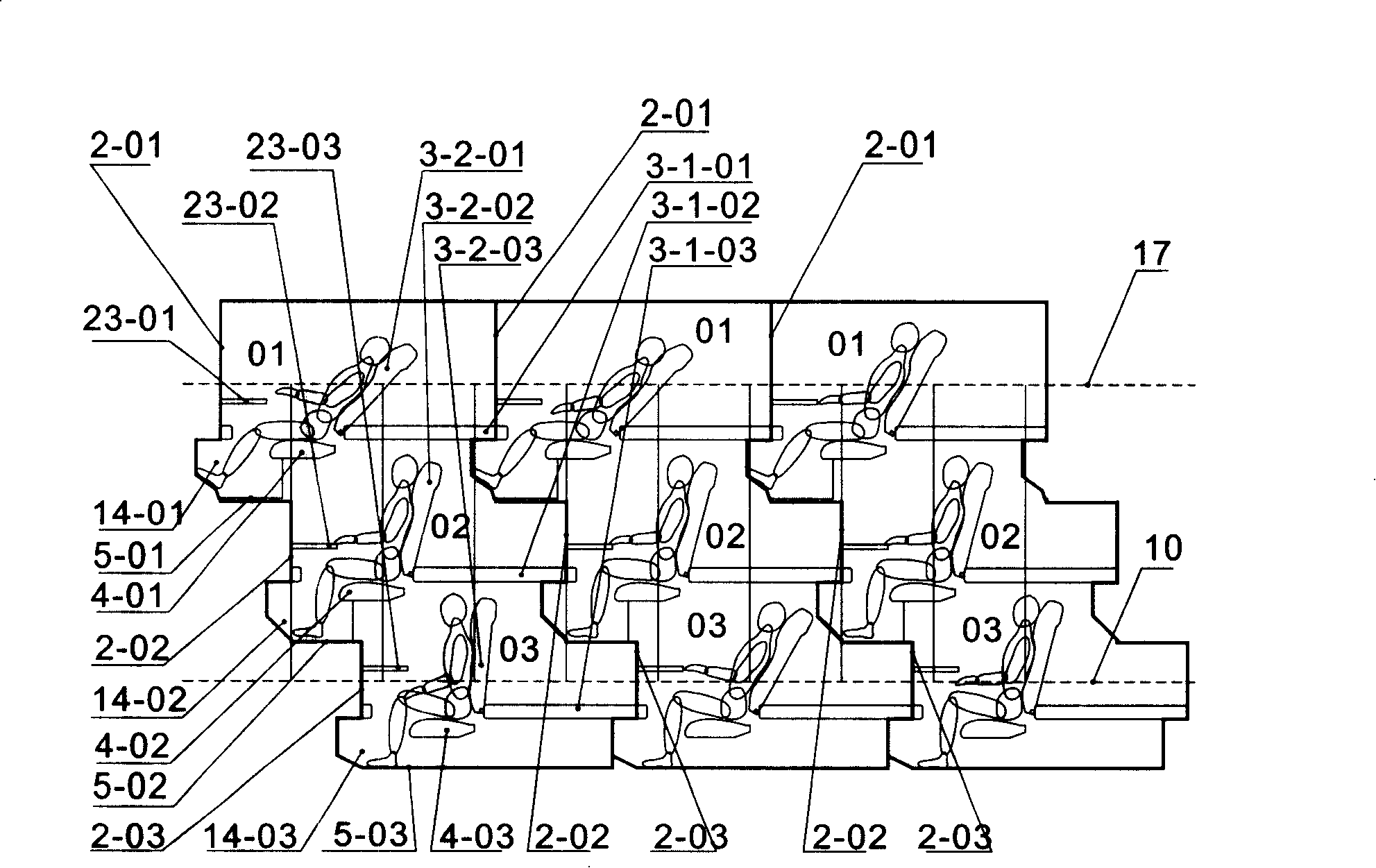
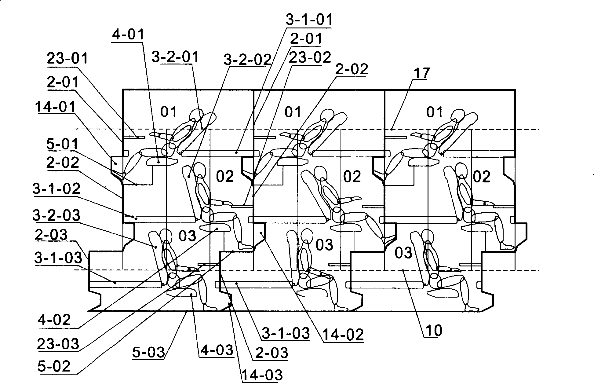
[0133] According to the basic features of the present invention, a bunk layout scheme of a three-layer sleeping cabin is as follows: figure 1 As shown, the head and tail of all the beds in this scheme have the same orientation, and the upper and lower floors are misaligned with each other, and the misalignment range is about a quarter of the length of a sleeping cabin, which is about 0.5 meters. Partition wall 2 is shared between adjacent sleeping cabins on the same floor. The foot hole 14-01 and the floor 5-01 in the top sleeping cabin 01 are just embedded in the upper space between the fixed bed board 3-1-02 of the middle sleeping cabin 02 below it and the partition wall 2-02 at the end of the bed. The space is partially occupied, which has the least impact on the lying activities of people living in the middle sleeping cabin. The foot hole 14-02 in the middle-level sleeping cabin 02 also just embeds the upper space between the fixed bed board 3-1-03 of the bottom sleeping ...


PUM


Abstract

The invention relates to a three-layer lying chamber used in railway, passenger vessel and hotel. The layers of the lying chamber are arranged besides the high arrangement corridor in a same direction and are staggered. A bottom lying chamber in the corridor floor 10 is communicated with the corridor through stairs; a top lying chamber is communicated with the corridor floor 10 through a platform 9 and a ladder step 11. A space is kept for stretching the body at the side of each bed in the lying chamber and the chamber is more convenient to pass in and out than the existing three-layer hard sleeper chamber. Each chamber can be closed by a movable gate 15; a turnover bedplate 3-2 articulated on a fixed bedplate of the bed in the laying chamber and a seat station 4 in the lower place can be conversed into an angle-adjustable back rest chair with handrails; furthermore, the lying chamber also has a table 23 and a foot extension hole 14. In a single carriage, 66 sealed and isolated single lying chambers can be arranged, besides, each carriage has condition of lying, sleeping, sitting and standing, as well as a special luggage chamber, which is suitable for equipping audiovisual device and surfing the internet.

Description

technical field [0001] The invention belongs to a sleeping cabin with a three-layer structure, in particular to a sleeping cabin with combined upper, middle and lower bunks in passenger vehicles such as railway passenger cars and passenger ships and fixed buildings. Background technique [0002] Three-berth sleeping compartments are common in long-distance railway sleeping cars. In addition, it can also be seen in passenger ships and special hotel rooms and dormitories. The main purpose of adopting the three-layer berth method is to maximize the space utilization rate on the premise of ensuring the most basic sleeper environment for passengers. In the current Chinese standard Type 25 railway hard sleeper carriages, the arrangement of sleepers is to arrange 11 open or semi-closed sleeper rooms by one side wall of the carriage, and each sleeper room has two rows separated by the partition walls on both sides. three berths. Passengers in the middle and upper berths can step ...

Claims


Application Information

Patent Timeline
IPC IPC(8): B61D1/08B60N2/005B63B29/02
CPCB61D1/08B61D31/00Y02T30/00
Inventor 于君
Owner 于君
Why Eureka
Try Eureka