Motorcycle power supply switch flameout circuit

A technology for power switches and motorcycles, used in spark ignition controllers, vehicle components, engine ignition, etc., can solve the problems of limited service life of contacts, increased product failure range, unfavorable miniaturization, and automated design, etc. Simple and reliable circuit

Inactive Publication Date: 2008-08-06
刘伟亮
View PDF0 Cites 4 Cited by
  • Summary
  • Abstract
  • Description
  • Claims
  • Application Information

AI Technical Summary

Problems solved by technology

[0002] In the current prior art, the motorcycle ignition switch is the simplest and also adopts a double-pole double-throw switch to realize closing the whole vehicle power supply and extinguishing the engine by shorting the flameout control terminal to the ground; Affecting the normal switch and flameout function of the car key, three relays are used to switch the switch and flameout function of the whole vehicle power supply, one normally open relay is used for the whole vehicle power switch, one normally closed relay and the other normally open The type relay is used to turn on the flameout wire and ground the flameout wire, so as to achieve the functions of keyless driving, remote start, remote flameout and anti-robbery; especially, the active device cannot be solved to close the flameout circuit when the battery is damaged and the circuit has no power supply. problem, so the flameout circuit can only be closed by using the relay contact in the case of no power supply and the relay reset function
Due to too many switch contacts, complex structure, too many relays, large volume, high cost, and limited service life of contacts, it not only increases the fault range of the product, but also is not conducive to the miniaturization and automation design of the product.

Method used


Image

  • Motorcycle power supply switch flameout circuit
  • Motorcycle power supply switch flameout circuit
  • Motorcycle power supply switch flameout circuit

Examples


Embodiment Construction

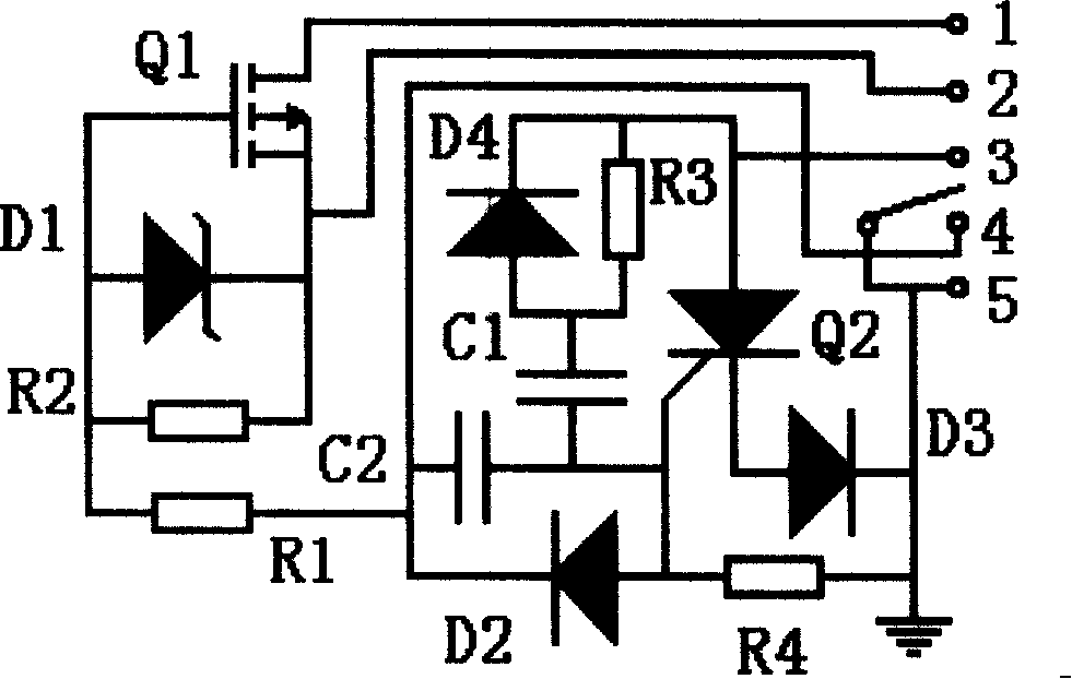
[0014] figure 2 The described motorcycle power switch flameout circuit is an embodiment of a non-contact ignition switch, including: a whole vehicle power switch circuit, a single-pole single-throw switch controlled by a car key, an isolation circuit, and a flameout control circuit.

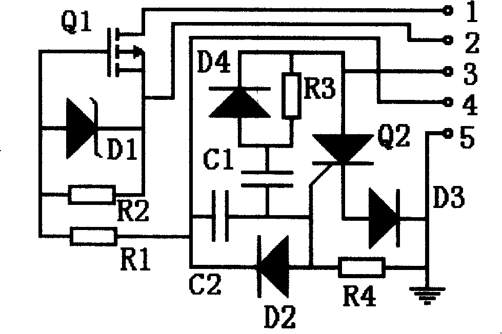
[0015] The whole vehicle power switch circuit is composed of a P-channel field effect transistor Q1, a 15V Zener diode D1, and resistors R1 and R2, the source of the power switch tube is connected to the positive pole 2 of the battery, and the drain is connected to the whole vehicle power supply 1. The system ground terminal 5 is connected to The negative electrode of the battery, Zener diode D1 and resistor R2 are connected in parallel between the source and gate of field effect transistor Q1. Zener diode D1 is to protect the source-gate voltage of the field effect transistor from exceeding 15V, and resistor R1 is the voltage regulator of diode D1. The current limiting resistor prevents the vol...


PUM


Abstract

The invention discloses a motorcar power switch flameout circuit, which is characterized in that a field effect tube whose source electrode is connected with a battery anode, drain electrode is connected with a whole-car power can be a power switch tube, a single-way thyristor anode is connected with a flameout line whose cathode is connected with ground and gate electrode is connected on the flameout line through a resistance and a diode by capacitance, the needed trigger current can be acquired. When the power control end makes the power switch tube conduct the whole-car power and the current triggers the ground short-circuit thyristor which stops and breaks the flameout line, the vehicle can be normally started. When the whole-car flameout is closed and the control of the thyristor trigger electrode is broken, the ignition power on the flameout line trigger and conduct the thyristor and the flameout line grounds short-circuit and the vehicle flames out and can't be started. The circuit has no trigger point, no static power consumption and is low in cost, which has wide prospect in the application fields such as motorcar burglarproof device, ignition switch, motorcar automatic control and the like.

Description

technical field [0001] The invention relates to a motorcycle power switch flameout circuit, in particular to a motorcycle power switch flameout circuit which is controlled by an active device in a passive state and has no static power consumption. Background technique [0002] In the current prior art, the motorcycle ignition switch is the simplest and also adopts a double-pole double-throw switch to realize closing the whole vehicle power supply and extinguishing the engine by shorting the flameout control terminal to the ground; Affecting the normal switch and flameout function of the car key, three relays are used to switch the switch and flameout function of the whole vehicle power supply, one normally open relay is used for the whole vehicle power switch, one normally closed relay and the other normally open The type relay is used to turn on the flameout wire and ground the flameout wire, so as to achieve the functions of keyless driving, remote start, remote flameout a...

Claims


Application Information

Patent Timeline
IPC IPC(8): F02P11/04B60R25/04
Inventor 刘伟亮
Owner 刘伟亮
Why Eureka
Try Eureka