
Method for manufacturing semiconductor device

A manufacturing method, semiconductor technology, applied in semiconductor/solid-state device manufacturing, semiconductor devices, electric solid-state devices, etc., can solve problems such as wiring layer resistance changes, EPROM reliability degradation, etc., and achieve the effect of preventing changes or reliability degradation

Inactive Publication Date: 2008-08-06
SANYO ELECTRIC CO LTD +1
View PDF1 Cites 4 Cited by
  • Summary
  • Abstract
  • Description
  • Claims
  • Application Information

AI Technical Summary

Problems solved by technology

Then, in the EPROM area, the interlayer insulating film is removed, resulting in the exposure of the wiring layer located under the pad electrode.
When the wiring layer is exposed, there is a problem that the reliability of EPROM is deteriorated due to the intrusion of moisture, etc.
In addition, since the exposed wiring layer is damaged by etching, there is also a problem that the resistance of the wiring layer changes.

Method used


Image

  • Method for manufacturing semiconductor device
  • Method for manufacturing semiconductor device
  • Method for manufacturing semiconductor device

Examples


Embodiment Construction

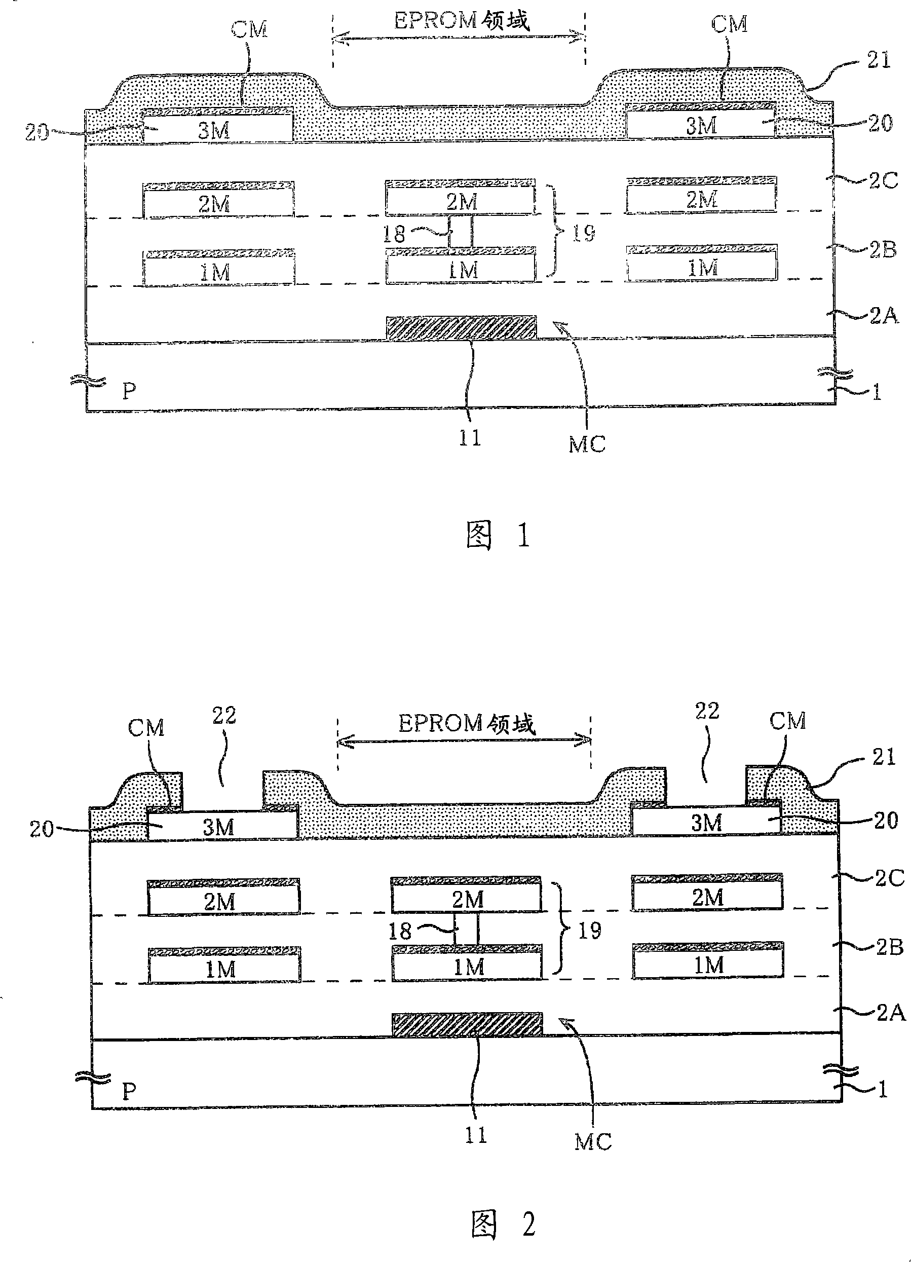
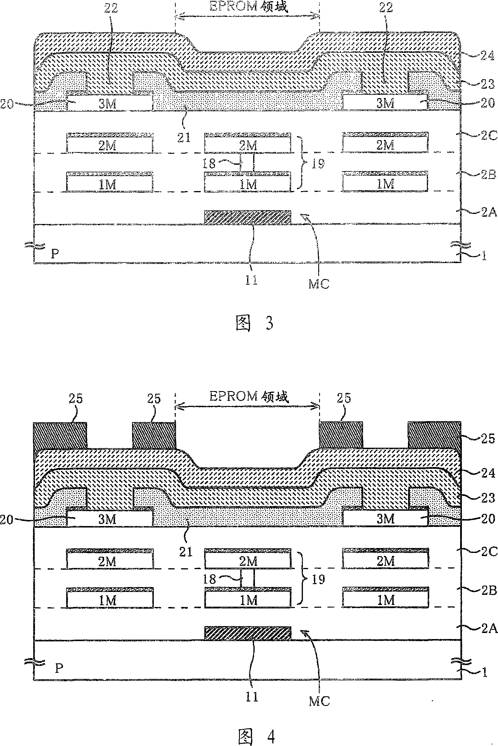
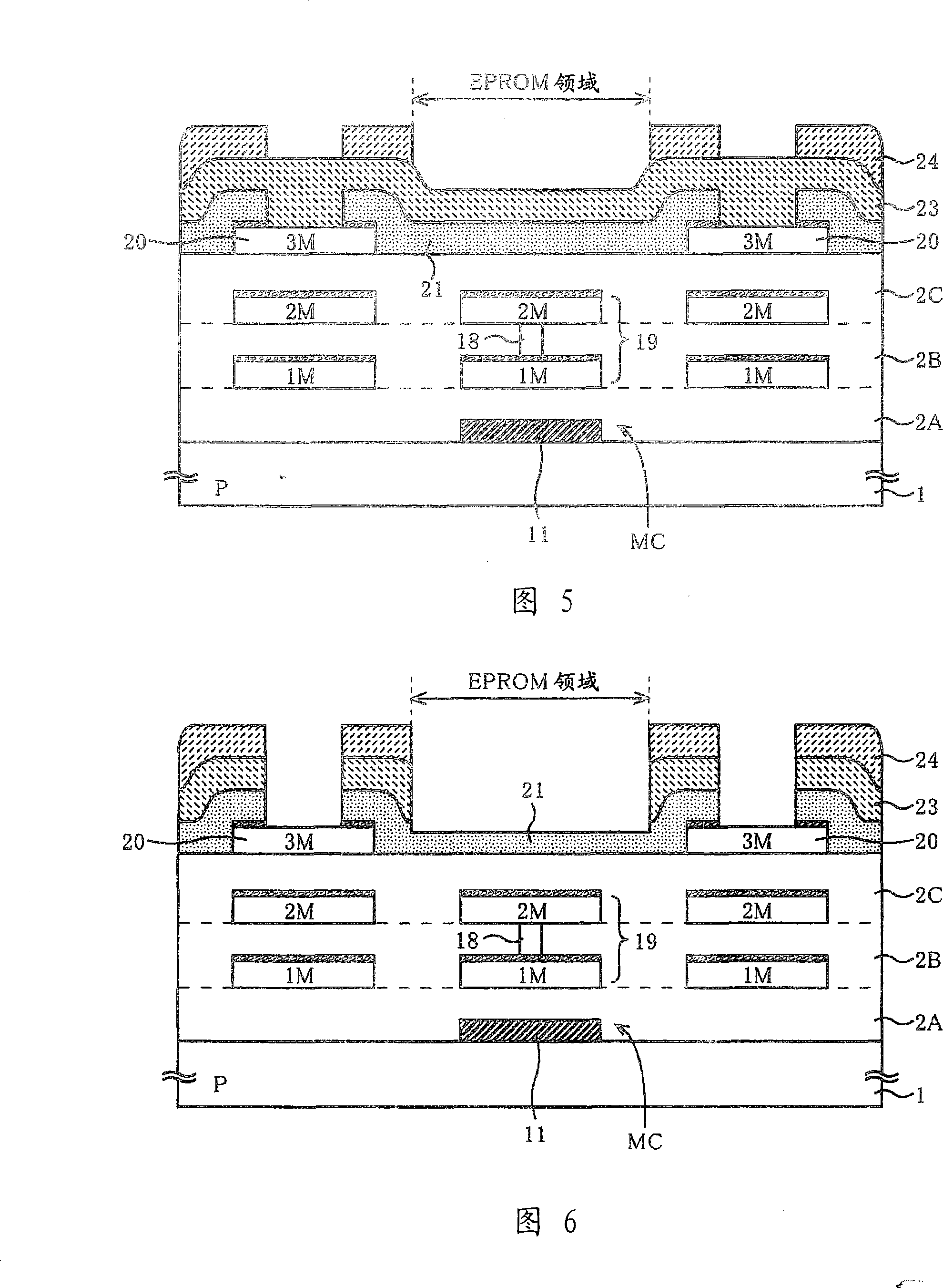
[0038] Next, a method of manufacturing a semiconductor device according to an embodiment of the present invention will be described with reference to the drawings.

[0039] As shown in FIG. 1 , memory cells MC are formed in the EPPOM region on the P-type semiconductor substrate 1 . Although there are actually a plurality of memory cells MC, FIG. 1 schematically shows only one floating gate 11 of the memory cell MC. This semiconductor device is formed by a three-layer metal process, a first metal layer 1M, a second metal layer 2M, and a third metal layer 3M on the floating gate 11 of the memory cell MC with interlayer insulating layers 2A, 2B, 2C formed. Interlayer insulating layers 2A, 2B, and 2C are formed of, for example, a laminated film of TEOS film / SOG film / TEOS film (film thickness about 950 nm), and are planarized. In addition, interlayer insulating layers 2A, 2B, and 2C have a property of transmitting ultraviolet rays.

[0040] The structure of the memory cell Mc wi...


PUM


Abstract

A method of manufacturing a semiconductor device that prevents exposure of a wiring layer in a memory region and prevents variation in wiring resistance and deterioration in reliability. An SiO2 film (21) is formed on the pad electrode (20) and the interlayer insulating film (2C) as an etching stopper film through which ultraviolet rays can pass. Afterwards, the SiO2 film (21) on the pad electrode (20) is selectively etched away, leaving the SiO2 film (21) on the EPROM area. Afterwards, on the SiO2 film (21) and on the pad electrode (20) that has removed the SiO2 film (21), form a silicon nitride film (23) and a polyimide film (24) as a protective film that cannot pass through the ultraviolet rays . After that, the silicon nitride film (23) and the polyimide film (24) on the pad electrode (20) and the EPROM area are selectively etched away. At this time, since the SiO2 film (21) acts as an etching stopper film, it can prevent the interlayer insulating film (2C) under the SiO2 film (21) from being removed to cause the control gate line metal layer (19) to be exposed.

Description

technical field [0001] The invention relates to a method for manufacturing a semiconductor device, in particular to a method for manufacturing a semiconductor device with an ultraviolet erasable non-variable memory unit. Background technique [0002] Ultraviolet-erasable EPROM is a memory capable of erasing electrically written information by irradiating ultraviolet rays, and is formed on a semiconductor substrate in the form of a single body or other semiconductor integrated circuits, such as built in a microcomputer. [0003] On the semiconductor substrate on which such EPROM is formed, a silicon nitride film is often formed as a passivation film, and a polyimide film is formed as a stress buffer material for packaging. However, since these silicon nitride films and polyimide films are impermeable to ultraviolet rays, they cannot be erased from the EPROM if they exist on the EPROM area. Therefore, these films are etched away on the EPORM area. In addition, in order to re...

Claims


Application Information

Patent Timeline
Patent Type & Authority Applications(China)
IPC IPC(8): H01L21/8247H01L27/115
CPCH01L27/115H01L29/42324H01L29/66825H01L29/7881H10B69/00
Inventor 稻叶裕一山田裕森川成洋
Owner SANYO ELECTRIC CO LTD
Learn More