Positive activation converter

A forward converter, a technology of forward conversion, applied to instruments, conversion equipment with intermediate conversion to AC, conversion of DC power input to DC power output, etc., can solve problems such as the inability to directly apply the conversion circuit JFET drive circuit

Active Publication Date: 2008-08-06
VERTIV CORP
View PDF3 Cites 20 Cited by
  • Summary
  • Abstract
  • Description
  • Claims
  • Application Information

AI Technical Summary

Problems solved by technology

However, the existing JFET drive requires a good square wave input signal source, which cannot be directly applied to the JFET drive circuit with a relatively complex conversion circuit.

Method used


Image

  • Positive activation converter
  • Positive activation converter
  • Positive activation converter

Examples


specific Embodiment approach 1

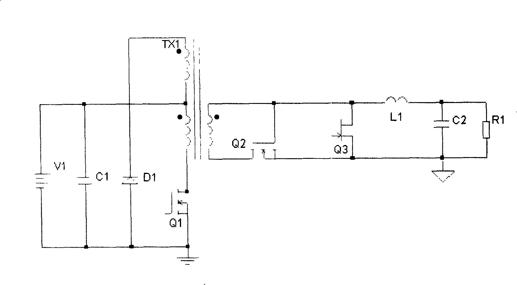
[0039] like Figure 2a As shown, the forward converter has the first basic form of drive circuit, and the input control loop uses the auxiliary winding to reset the forward circuit.

[0040] Among them, Q1 is an N-channel MOSFET main switching tube, Q2 is an N-channel MOSFET rectifier tube, and Q3 is an N-channel depletion type JEFET freewheeling tube. V1 is the input power supply, and the inductor C1 is used for input filtering, respectively connected to the positive and negative ends of the input power supply V1 with the same name. There are two windings on both sides of the primary and secondary sides of the transformer TX1 respectively. The two windings on the primary side are the primary winding and the demagnetizing winding respectively. The positive end of the main winding on the primary side (the end of the main winding on the primary side connected to the positive pole of the power supply is called the positive end, and the end with the same name is the positive end...

specific Embodiment approach 2

[0047] like Image 6 As shown, the forward converter has the second basic form of drive circuit, and the input control loop uses the auxiliary winding to reset the forward circuit. Except for the driving circuit, the structure of the forward converter of this embodiment is the same as that of the forward converter of the first embodiment.

[0048] The charging circuit part in the forward converter drive circuit includes a second diode D2, the discharging circuit includes a fourth diode D4 and a fifth diode D5, the positive terminal of the secondary auxiliary winding of the transformer is grounded, and its other One end is connected to the anode of the second diode D2 and the cathode of the fourth diode D4, the input end of the level coupling circuit is connected to the cathode of the second diode D2, the output end is connected to the gate of the freewheeling tube Q3, and simultaneously connected to the first Anode connection of five diodes D5.

[0049] In this embodiment, t...

specific Embodiment approach 3

[0053] like Figure 9 As shown, the forward converter has the third basic form of drive circuit, and the input control loop uses the auxiliary winding to reset the forward circuit. Except for the driving circuit, the structure of the forward converter of this embodiment is the same as that of the forward converters of the first and second embodiments.

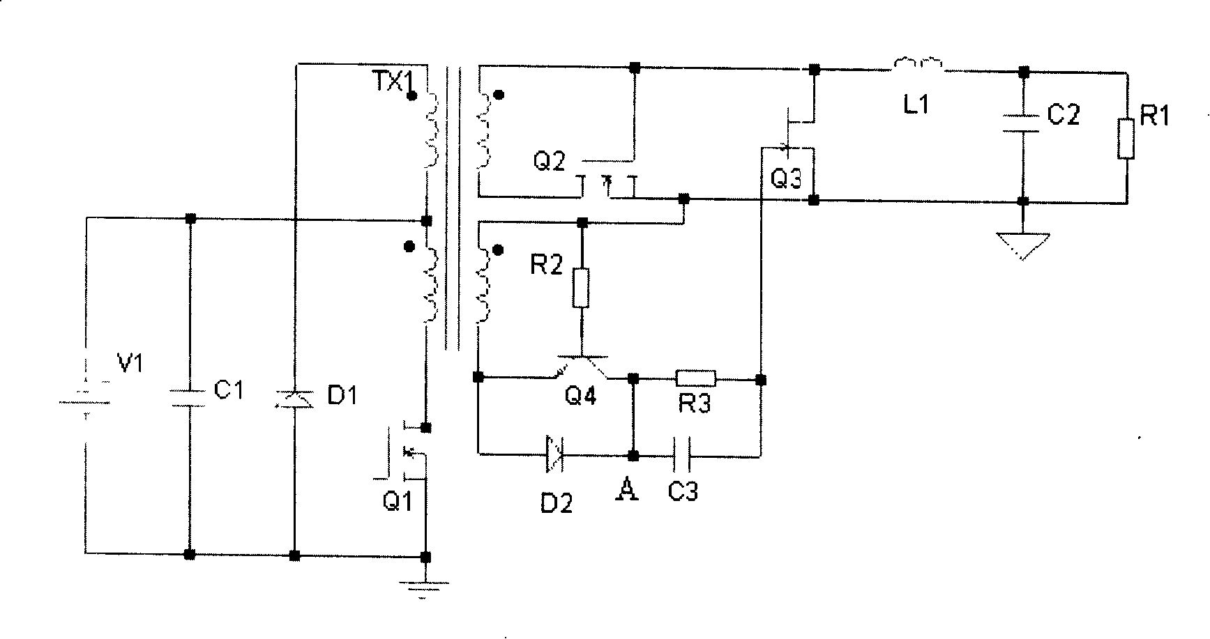
[0054] Different from the drive control signal in Embodiments 1 and 2 from the auxiliary winding on the secondary side of the transformer, the drive control signal in this implementation comes from the main winding on the secondary side of the transformer. In the drive circuit, the charging circuit includes a charging diode D2a, the discharging circuit includes a switching transistor Q4a, the emitter of the switching transistor Q4a is grounded, and its base is connected to the positive terminal of the secondary main winding of the transformer through a resistor R2a, and the anode of the charging diode D2a Connect the drain of ...


PUM


Abstract

The invention discloses a forward converter, which comprises a power source, an input control circuit, a transformer and a rectifier-filter circuit. The input control circuit has a main switching diode, and the rectifier-filter circuit comprises a rectifier tube and a N-channel JFET forward diode, and the gate of the rectifier tube and the drain of the forward diode are connected to a positive dotted terminal of a transformer secondary principal winding, and the drain of the rectifier tube is connected to the other end of the transformer secondary principal winding, and a source electrode of the forward diode and a source electrode of the rectifier are connected to a common output ground. The transformer has a secondary winding for outputting drive control signals, and a drive circuit for providing pulse drive signals to the forward diode is arranged between the secondary winding and the gate of the forward diode. On-and-off of the JFET forward diode is controlled by voltage signals of the transformer winding so that the forward converter works in a synchronous rectifier state. The drive signals are directly from the transformer winding so that no special driver is needed and no additional power supply is needed, which makes the forward converter simple and reliable.

Description

technical field [0001] The invention relates to a power conversion device using synchronous rectification technology, in particular to a forward converter. Background technique [0002] One of the most important developments in low-voltage power conversion in recent years has been the use of synchronous rectification. Compared with the traditional diode rectification method, the synchronous rectification technology greatly reduces the conduction voltage drop of the rectifier power device, thereby reducing the conduction loss of the rectifier device and improving the conversion efficiency of the converter. Due to the good characteristics of MOSFETs (Metal Oxide Semiconductor Field Effect Transistors), the current rectifiers and freewheeling tubes that implement synchronous rectification basically use MOSFETs with low on-resistance. Recently, a JFET (Junction Field Effect Transistor) suitable for synchronous rectification has appeared. Compared with traditional JFETs, the ne...

Claims


Application Information

Patent Timeline
Patent Type & Authority Applications(China)
IPC IPC(8): H02M3/28H02M3/335H02M3/338
Inventor 谢仁践
Owner VERTIV CORP
Why Eureka
Try Eureka