Axial flow impeller machine design method and blade

A technology of impeller machinery and design method, which is applied in the direction of mechanical equipment, reaction engines, blade support elements, etc., and can solve the problems of poor cavitation resistance and low efficiency of axial flow impellers

Inactive Publication Date: 2008-08-20
任明琪
View PDF0 Cites 21 Cited by
  • Summary
  • Abstract
  • Description
  • Claims
  • Application Information

AI Technical Summary

Problems solved by technology

This will inevitably lead to poor cavitation resistanc

Method used


Image

  • Axial flow impeller machine design method and blade
  • Axial flow impeller machine design method and blade
  • Axial flow impeller machine design method and blade

Examples


Embodiment Construction

[0120] The details of the embodiments of the present invention will be described below by taking an axial-flow water pump as an example according to the accompanying drawings.

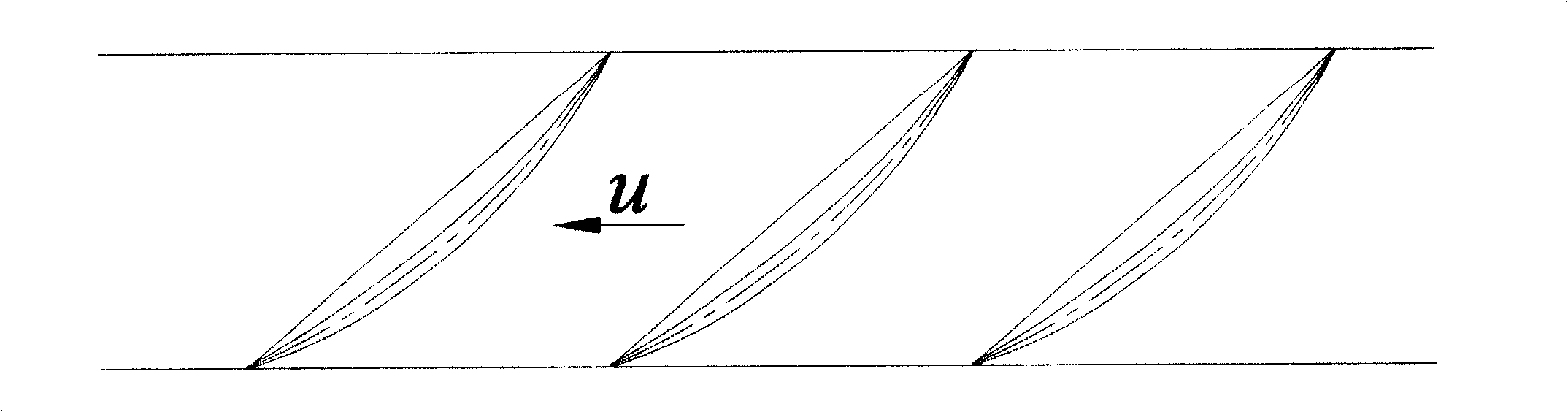
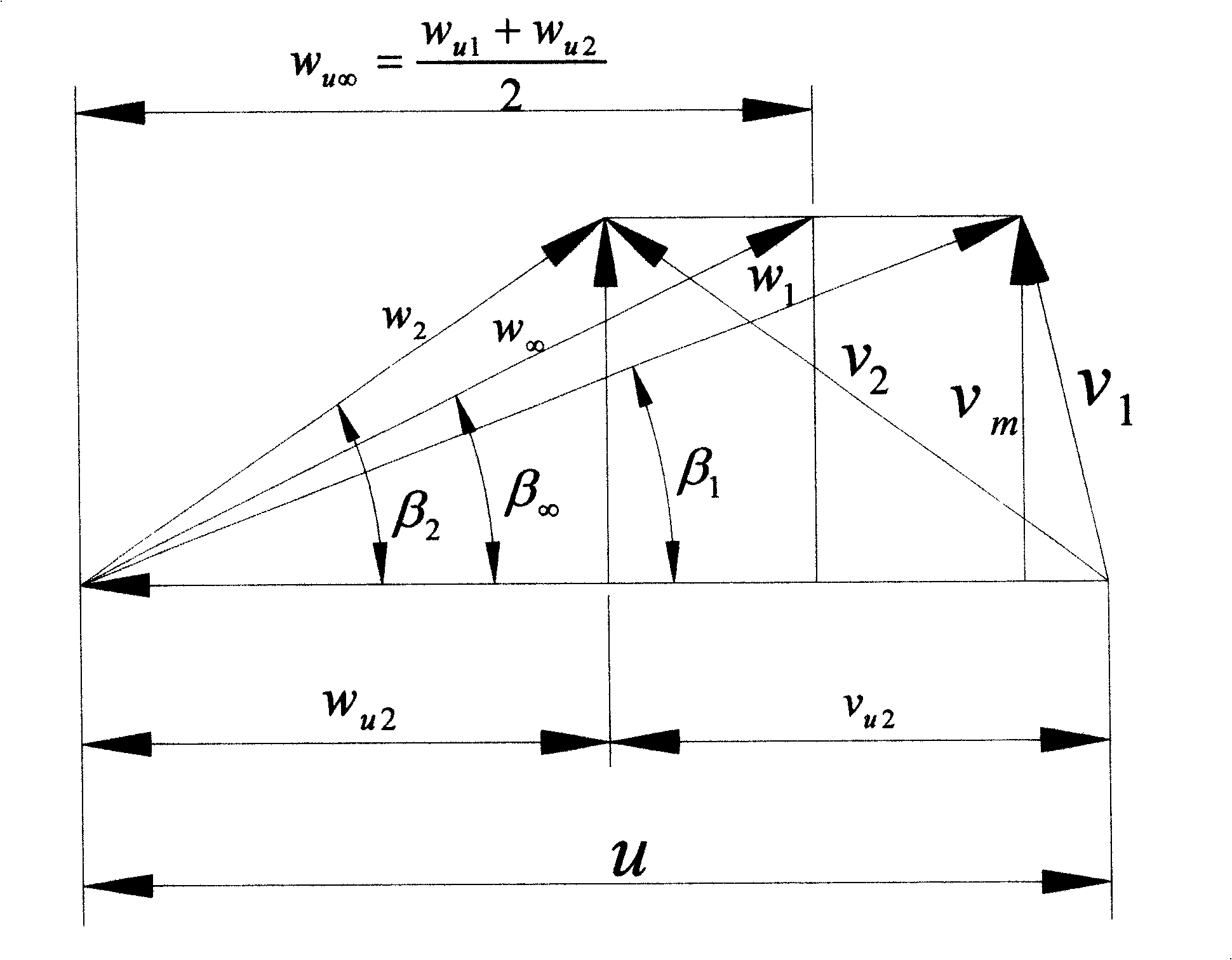
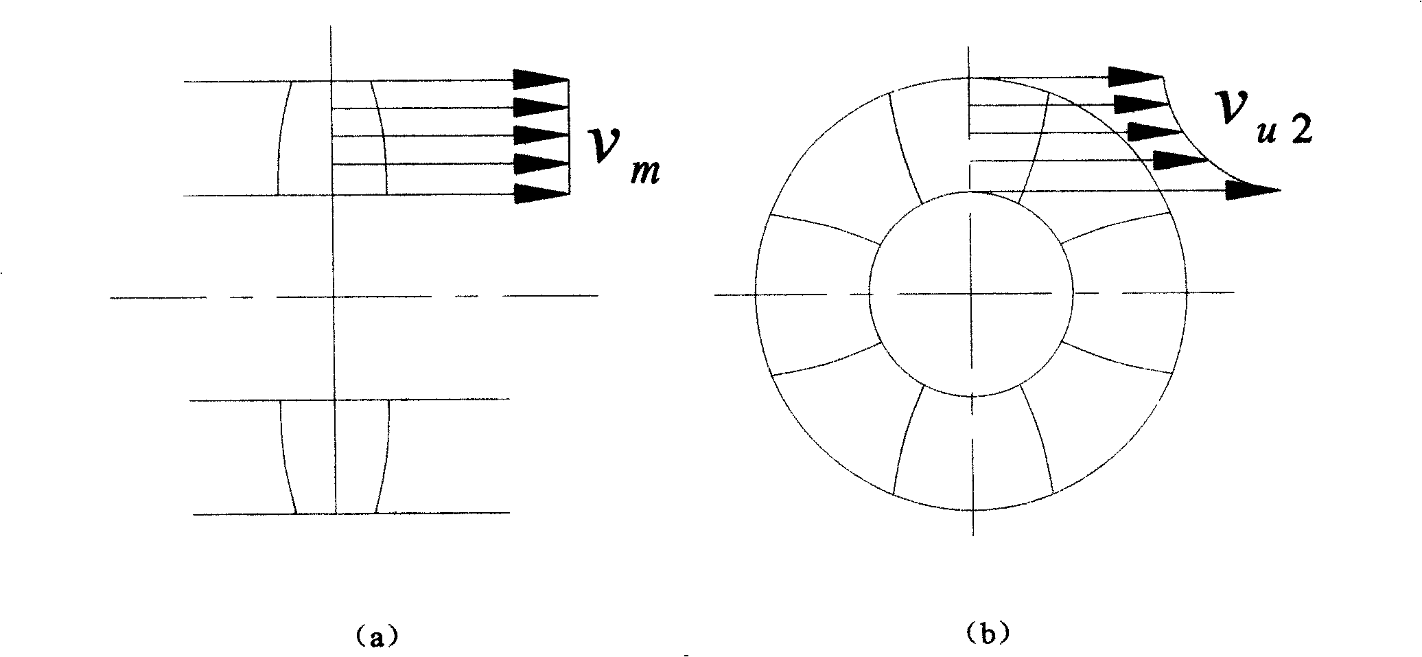
[0121] The inventor of the present invention believes that the closer the assumed flow model is to the actual flow field, the higher the efficiency of the axial-flow turbomachinery designed using this flow model will be. Therefore, the flow model of the present invention is assumed as follows: (1) fluid is ideal incompressible fluid; (2) fluid particle flows on the cylindrical surface taking impeller axis as center line; (3) rotating speed, torque of impeller machinery , flow, etc. do not change with time; (4) the flow is axisymmetric; (5) the circumferential component v at the blade outlet u2 and shaft speed v m2 Linearly distributed along the radial direction of the blade, and the circumferential component and axial surface velocity at the hub side are small, while the circumferential component and ...


PUM


Abstract

The invention provides a design method for an axial flow impeller machine for confirming the flow model of the axial flow impeller machine. The method at least includes the circle component of vu2 and axial plane speed of vm2 which are at the exit of a vane and are distributed in a way of linearity along the radius of the vane, and the circle component and axial plane at the hub side is small while the circle component and axial plane at the wheel edge side is larger; the distribution functions of the circle component vu2 and axial plane speed vm2 at the exit of the vane are confirmed according to the external characteristic parameters and structure parameters as well as the flow model of the axial flow impeller machine; the axial flow impeller machine is designed according to the confirmed distribution functions of the circle component vu2 and axial plane speed vm2 at the exit of the vane. The invention also provides the vane of the designed axial flow impeller machine; wherein, the difference of the mounting angles for the wing models of the hub side and wheel edge side of the vane Delta Beta is equal to Beta h minus Beta s and is between minus 3 degrees to 10 degrees. The equipressure area at the back of the vane is distributed along the radial direction of the vane in strip. The invention can improve the efficiency of the impeller machine to reach 91 percent and improve the anti-cavitation erosion capacity.

Description

technical field [0001] The invention relates to a design method and a blade of an axial-flow impeller machine, belonging to the technical field of fluid machines. Background technique [0002] In the past, when people designed axial-flow impeller machinery, they mainly used the lift method or the arc method. No matter what method is used, it is assumed that the fluid particles flow on the cylindrical surface with the impeller axis as the centerline, and the motions of the fluid particles on adjacent cylindrical surfaces are independent of each other. According to the assumption of the independence of the cylindrical layer, the complex motion in the impeller can be simplified to study the flow on the cylindrical surface, and the cylindrical surface is the flow surface. Make multiple such cylindrical flow surfaces in the impeller, the flow on each flow surface may be different, but the research method is the same. Such as figure 1 As shown, the cylindrical surface intersect...

Claims


Application Information

Patent Timeline
IPC IPC(8): F01D5/14F04D29/24F04D29/38F03B3/12
CPCY02E10/20
Inventor 任明琪
Owner 任明琪
Why Eureka
Try Eureka