Enclosed cavity type heat exchanger

A closed cavity and heat exchanger technology, applied in the field of liquid-liquid heat exchange and in-tube reaction, can solve the problems of increased equipment cost, low heat transfer coefficient, increased heat exchanger cost, etc., to achieve cost saving, efficient heat transfer, simple structure

Inactive Publication Date: 2008-08-20
上海释皆通生物科技有限公司
View PDF0 Cites 16 Cited by
  • Summary
  • Abstract
  • Description
  • Claims
  • Application Information

AI Technical Summary

Problems solved by technology

However, the existing wall-type heat exchange structure for cold and hot fluids determines that it has the following inherent disadvantages: for liquid-liquid heat exchangers, the heat transfer coefficient of the shell side is usually low, resulting in a low overall heat transfer coefficient. The thermal area will increase the equipment cost; for the shell-and-tube heat exchanger with high pressure on the shell side, due to the large diameter of the shell, the thickness of the shell will increase, which will increase the cost of the heat exchanger; in the field of low-grade energy recovery, Due to the small heat transfer temperature difference, the efficiency of the shell-and-tube heat exchanger is even lower; in terms of temperature control, such as: process fluid outlet temperature control and physical or chemical reactions in the heat exchange tube, the traditional shell-and-tube heat exchanger The performance is that the temperature response is lagging, and the control is difficult
In addition, various heat transfer enhancement measures of the existing shell-and-tube heat exchanger have greatly increased its manufacturing difficulty and equipment cost.

Method used


Image

  • Enclosed cavity type heat exchanger
  • Enclosed cavity type heat exchanger
  • Enclosed cavity type heat exchanger

Examples


Embodiment Construction

[0016] The present invention will be further described now in conjunction with accompanying drawing

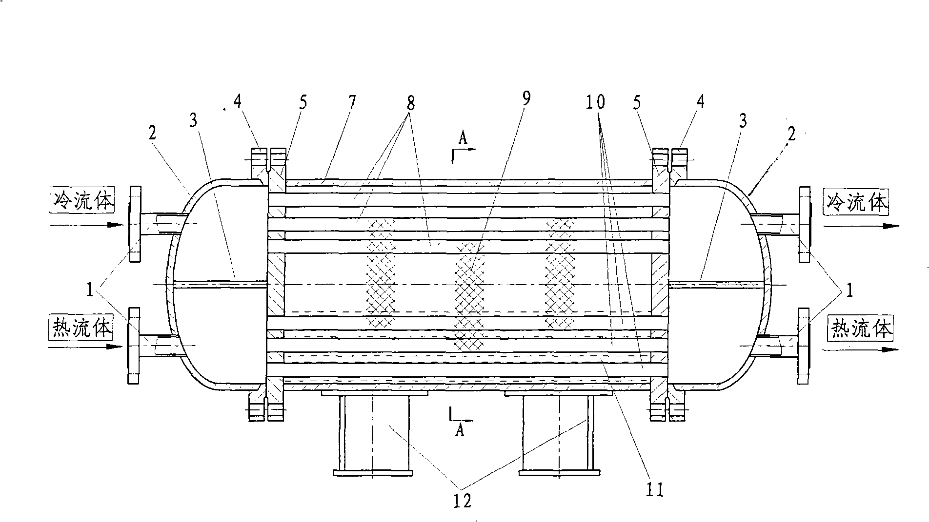
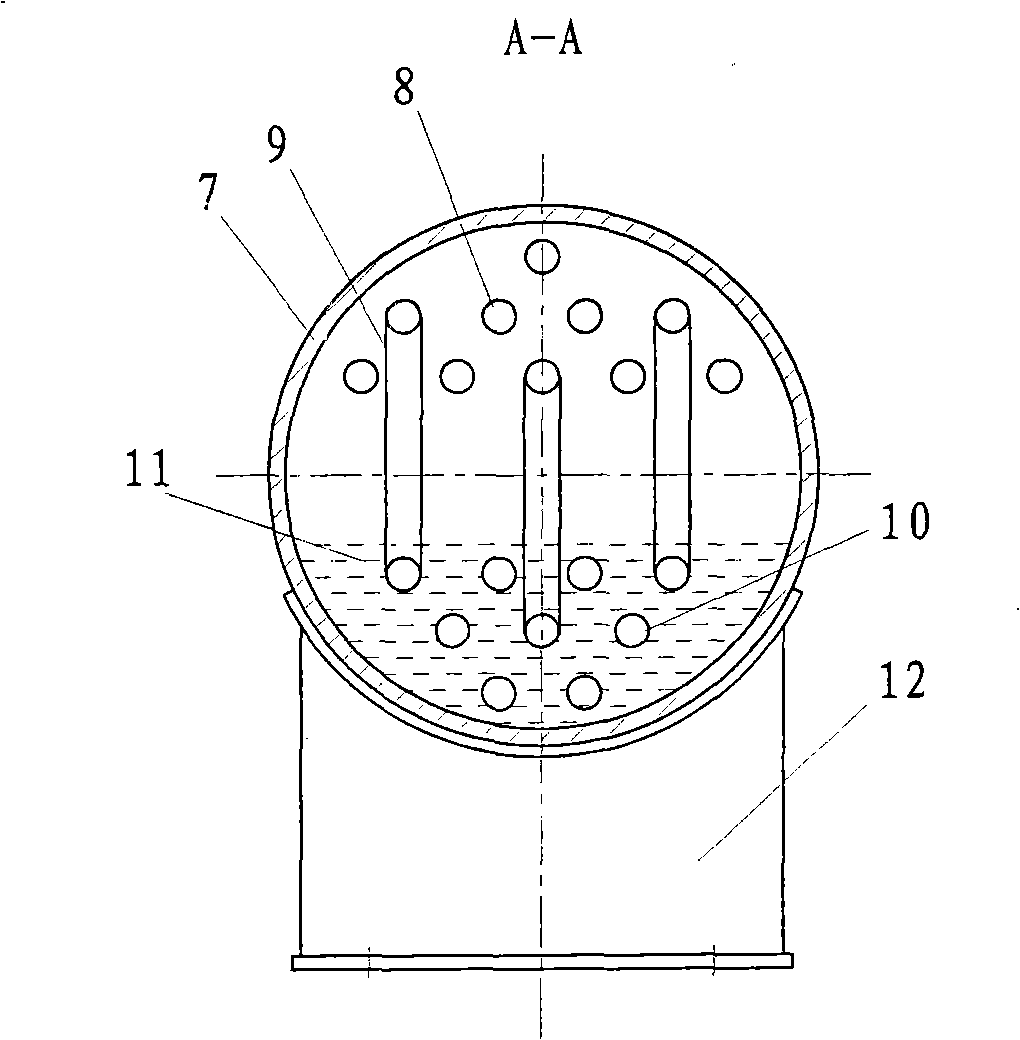
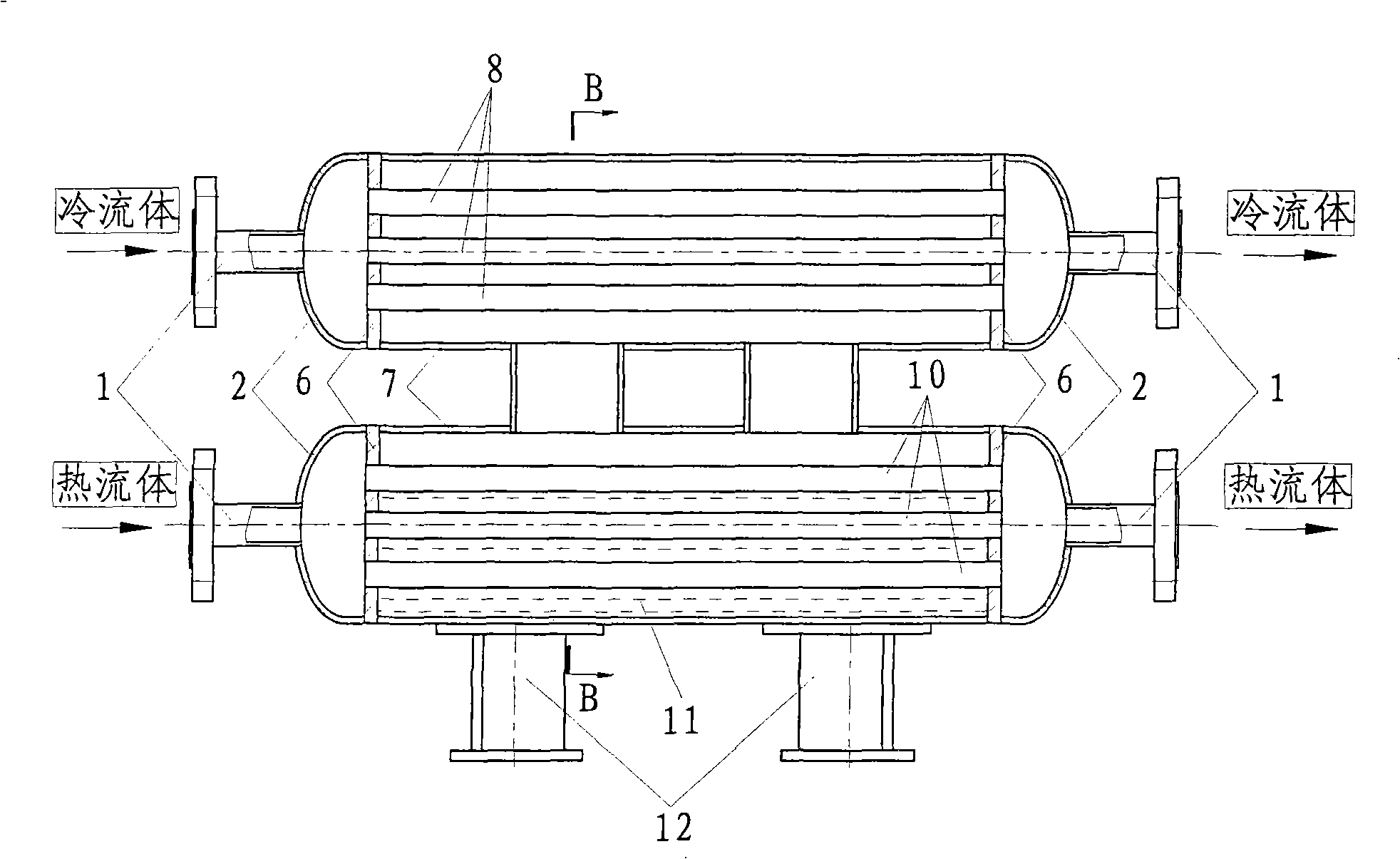
[0017] The closed cavity heat exchanger includes a vacuum sealed cavity, a heat exchange tube bundle, a working medium and a casing used as a fluid channel. Its structure is: the two ends of the orifice plate 5 and the horizontal cylindrical shell 7 are sealed, and the cold fluid heat exchange The tube bundle 8 and the hot fluid heat exchange tube bundle 10 pass through the orifice plate 5 and seal to form a cavity; the cold fluid heat exchange tube bundle 8 is located in the upper space of the cavity, and the hot fluid heat exchange tube bundle 10 is located in the lower space of the cavity; the vacuum state The airtight chamber of the cylinder is filled with working medium 11; the inner cavity of the cold and hot fluid heat exchange tube bundles communicates with the casing 2 with the connection pipe 1 at both ends, forming independent fluid passages respectively; the outer b...


PUM


Abstract

The invention provides a closed chamber typed heat exchanger, belonging to the heat energy exchange technical field. The closed chamber typed heat exchanger is characterized in that a hole plate is sealed with two ends and the circumference of a cylindrical shell which is horizontally arranged; a cold fluid heat exchange pipe bundle and a hot fluid heat exchange pipe bundle pass through the hole plate and are sealed to form a chamber body; the cold fluid heat exchange pipe bundle and the hot fluid heat exchange pipe bundle are respectively arranged in the upper space and the lower space of the chamber body; a vacuum-shaped closed chamber is filled with working media; the internal chambers of the cold fluid heat exchange pipe bundle and the hot fluid heat exchange pipe bundle are communicated with a cover with a connecting pipe at two ends so as to respectively form an independent fluid passage; an installation supporter is welded externally below the cylindrical shell; the closed chamber of the cylindrical shell can be provided with a plurality of structural types such as single body, double bodies or three bodies; the closed chamber typed heat exchanger has the active effects that the heat exchanger is not a pipe shell typed heat exchanger in traditional meaning and has the advantages of simple structure, fast response, convenient heat control, high heat transmission efficiency and obvious energy-saving effect. The heat exchanger can be applied to heat transmission places with low, middle and high temperature, and is an extremely practical invention.

Description

technical field [0001] It belongs to the technical field of heat energy exchange, specifically a technology related to liquid-liquid heat exchange and internal reaction in tubes. Background technique [0002] At present, as a mature and standardized pressure-bearing heat exchange equipment, the shell-and-tube heat exchanger is used in various fields of industry. However, the existing wall-type heat exchange structure for cold and hot fluids determines that it has the following inherent disadvantages: for liquid-liquid heat exchangers, the heat transfer coefficient of the shell side is usually low, resulting in a low overall heat transfer coefficient. The thermal area will increase the equipment cost; for the shell-and-tube heat exchanger with high pressure on the shell side, due to the large diameter of the shell, the thickness of the shell will increase, which will increase the cost of the heat exchanger; in the field of low-grade energy recovery, Due to the small heat tra...

Claims


Application Information

Patent Timeline
Patent Type & Authority Applications(China)
IPC IPC(8): F28D7/00
Inventor 马永锡
Owner 上海释皆通生物科技有限公司
Why Eureka
Try Eureka