
Process equipment for roller brush

A technology of processing equipment and roller brush, which is applied in the bonding method of adhesive heating, the device of coating liquid on the surface, construction, etc., can solve the problems of poor bonding fastness, easy degumming, high processing cost, etc. Achieve the effects of reducing the number of start and end times, simple manufacturing process, and low production cost

Inactive Publication Date: 2008-08-27
何朝良
View PDF1 Cites 16 Cited by
  • Summary
  • Abstract
  • Description
  • Claims
  • Application Information

AI Technical Summary

Problems solved by technology

[0004] However, in actual operation, it is found that: the disadvantage of the above-mentioned first method is that the production efficiency is low because the glue is painted by hand, and it is easy to cause the glue to be unevenly painted, and the glue is easy to fall off, so the waste of glue is large; Secondly, the bonding fastness is not good with manual brushing, and it is easy to degumming, which cannot ensure the bonding quality of the bristles; moreover, the core tube with a diameter of less than 20 mm cannot be fixed by hand.
The shortcoming of second kind of method is: when the helical line form of plush cloth is directly fixed on the beginning and the end of the core tube surface, the proficiency of the operator is required to be higher, otherwise, the loss of plush cloth at the two ends of the core tube is relatively large. Large, but the core tube only rotates, and its length is limited by the equipment, usually no more than 2 meters. Therefore, the production of the same number of roller brushes not only consumes a lot, but also requires continuous loading and unloading of the core tube, so the work efficiency is low. High manufacturing cost; in addition, for core tubes with a diameter smaller than 20 mm, the processing cost will be higher

Method used


Image

  • Process equipment for roller brush
  • Process equipment for roller brush
  • Process equipment for roller brush

Examples


Embodiment Construction

[0025] The present invention will be further described in detail below in conjunction with the accompanying drawings and embodiments.

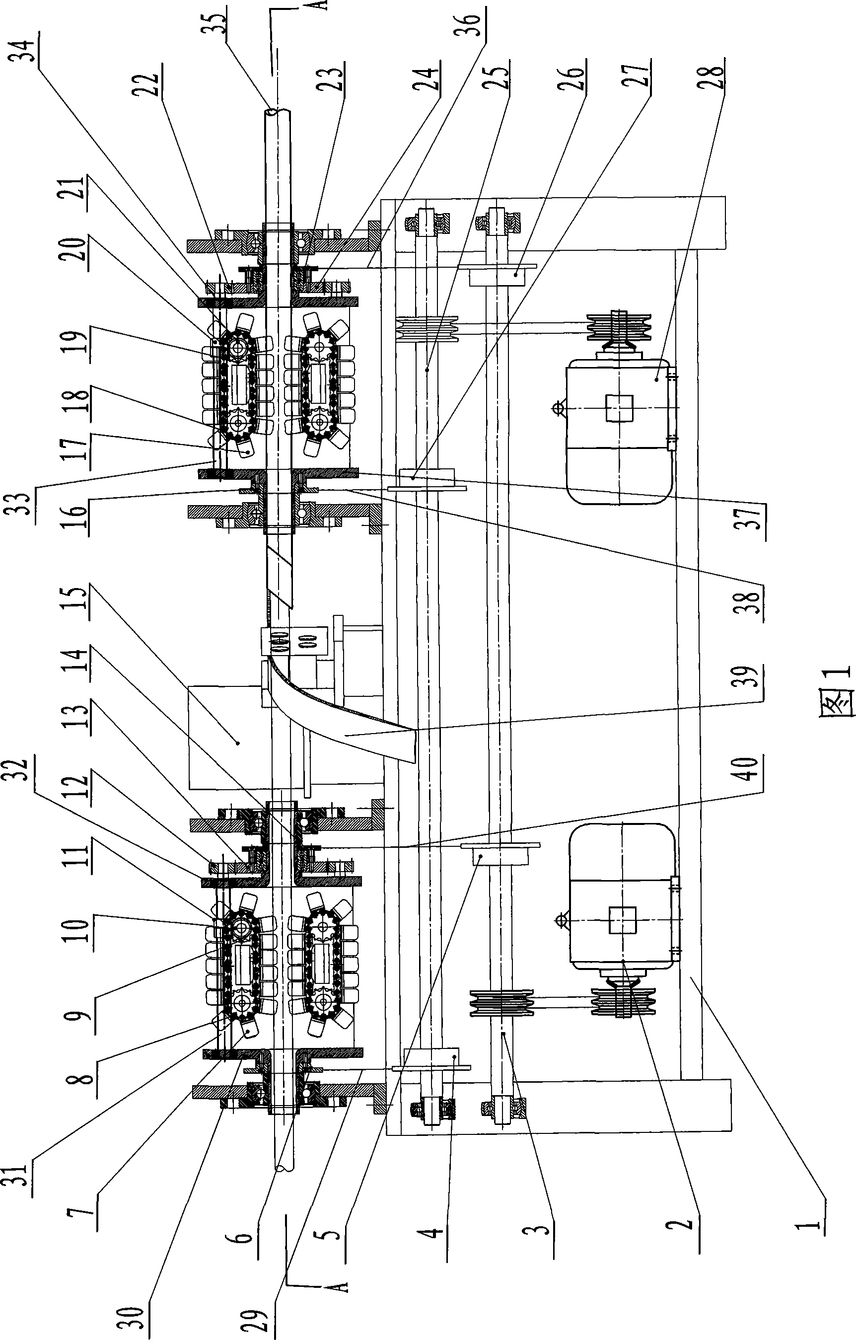
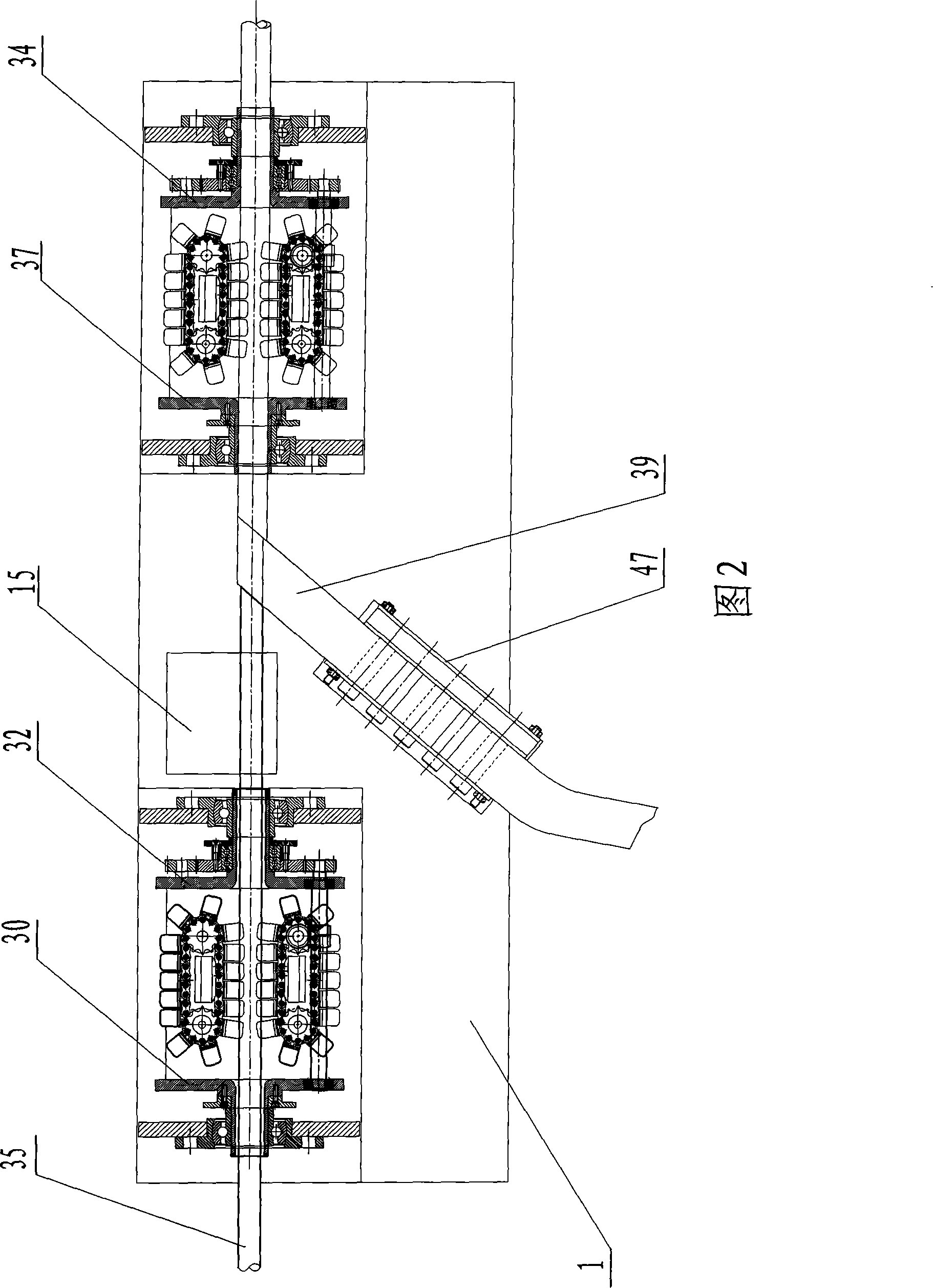
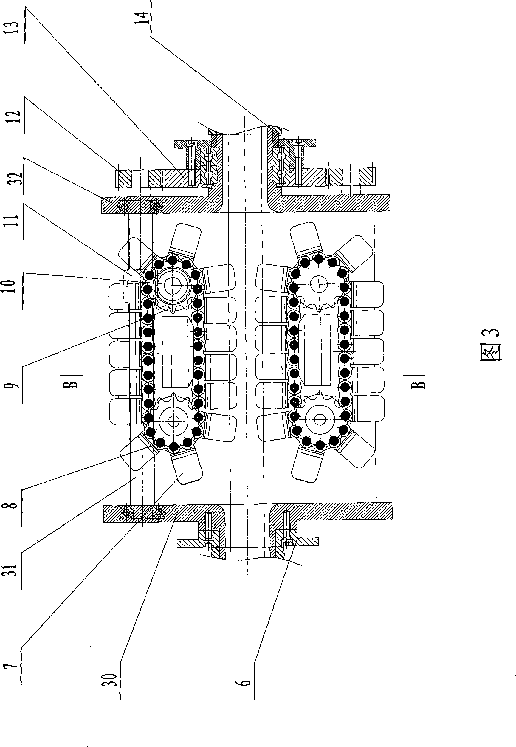
[0026] Fig. 1 and Fig. 2 have shown an embodiment of roller brush processing equipment of the present invention, are used for fixing the bristle that plush cloth 39 is made on core tube 35 surfaces, and it comprises organic frame 1, upper rubber cylinder 15, left drive The device, the right transmission device, and the axial movement device that drives the core tube to move axially and the rotation device that drives the core tube to rotate synchronously through the above-mentioned left and right transmission devices. Wherein, four bearings are arranged on the frame 1, and the core pipe 35 made of PVC is supported in the four bearings. Simultaneously, the first planetary carrier 30 and the second planetary carrier 32 are sleeved on the core tubes inside the first and second bearings, and the left planetary shaft 31 is arranged between the firs...


PUM


Abstract

Roller brush processing equipment is used to fix brush hair made of plush cotton flannel on the surface of a core tube. The equipment comprises a frame supporting the core tube and a sizing drum and a heater corresponding to the core tube, and is characterized in that: the left end and the right end of the frame are respectively provided with a left transmission device and a right transmission device which can realize friction movement and holding of the core tube; moreover, the frame is provided with an axial movement device which can synchronously drive the core tube to move in axial direction through the left transmission device and the right transmission device as well as a rotating device which can drive the core tube to rotate. After adopting the structure, the core tube can move in axial direction when rotating; therefore, the length of the core tube which is arranged on the frame is no longer limited by the equipment, and the core can be output forwards ceaselessly, thereby realizing the goal that plush cotton flannel can be stuck to the external surface of the core tube without stop; thus, the roller brush processing equipment reduces the start and end times of the plush cotton flannel on the surface of the core tube without frequently replacing the core tube, thereby having the characteristics of simple manufacture process, high operation efficiency and low operation difficulty; moreover, the equipment ensures that a processed roller brush has low production cost and has stronger market competitive power.

Description

technical field [0001] The invention relates to a roller brush processing equipment for wall painting, in particular to a roller brush processing equipment for fixing bristles on the surface of a core tube. Background technique [0002] There are many types of roller brush structures for building decoration, most of which include a core tube, on the outside of which the core tube is fixed with bristles made of plush cloth; the bristles are used to paint walls. [0003] At present, there are mainly two processing methods for fixing the above-mentioned bristles on the surface of the core tube: the first method is to adopt a hand-made method, that is, the core tube is first fixed on a top device with two ends coaxial, and then the The core tube rotates in the top device, glue is applied to the outer surface of the core tube with a brush, and then the plush cloth is manually stuck on the outer surface of the core tube. After the glue dries, the core tube with plush cloth is cut...

Claims


Application Information

Patent Timeline
IPC IPC(8): E04F21/06B05D7/24C09J5/06
Inventor 何朝良何普红陈国春
Owner 何朝良
Learn More