Oil smoke cleanse extraction device

A technology of exhaust device and oil fume purification, which is applied in the fields of oil fume removal, chemical instruments and methods, and household heating, etc., can solve the problems of oil fume gas purification, increased noise, and large working noise of range hoods, and achieves the elimination of pollution, The effect of silently eliminating oil fume

Inactive Publication Date: 2008-09-03
王君
View PDF0 Cites 24 Cited by
  • Summary
  • Abstract
  • Description
  • Claims
  • Application Information

AI Technical Summary

Problems solved by technology

To a certain extent, the environmental pollution caused by oil fumes in the kitchen has been removed for people, but there are some technical defects in the existing range hoods: at first, the range hoods do not effectively purify the smoke gas sucked. The exhausted oil fume will cause certain pollution to the surrounding environment, and sometimes the oily fume gas discharged to the outside will return to the kitchen through the doors and windows along with the air that is pressurized and flowed to the kitchen, especially in summer. ; Secondly, the existing range hoods will produce larger working noises during work, which will have a greater impact on the environment of the kitchen.
The rotating fan blades and the high wind pressure cause mechanical vibration noise and howling and resonance of the flowing air in the channel at the same time in the smoke exhaust pipe and the casing, further increasing the noise.
This application defect comes from the working principle and technical structure of the existing range hood

Method used


Image

  • Oil smoke cleanse extraction device
  • Oil smoke cleanse extraction device
  • Oil smoke cleanse extraction device

Examples


Embodiment 1

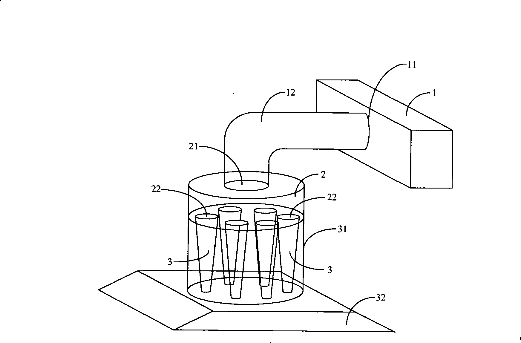
[0054] Such as figure 1 As shown, this embodiment includes a blower 1 for exhausting gas, the inlet 11 of the blower 1 is connected with the outlet 21 of a box-shaped air flow controller 2 through a pipe 12 . The airflow controller 2 is provided with a plurality of air intake holes 22 . Each air inlet 22 is respectively connected to the larger diameter end of a conical cyclone pipe 3 . Several cyclone pipes 3 are placed in a cabinet casing 31 , and an oil fume hood 32 is also provided below the cabinet casing 31 .

[0055] During work, the cabinet box body 31 with a plurality of cyclone tubes 3 inside, the oil fume hood 32 and the air flow controller 2 are installed above the cooktop together, and the end of the cyclone tube 3 with a smaller diameter is exhausted by the fan 1 The inhaled gas forms a negative pressure area in the fume hood 32 , so that the fume gas generated on the stove is sucked into the cyclone pipe 3 . The conical cyclone pipe 3 is a reducing pipe. The ...

Embodiment 2

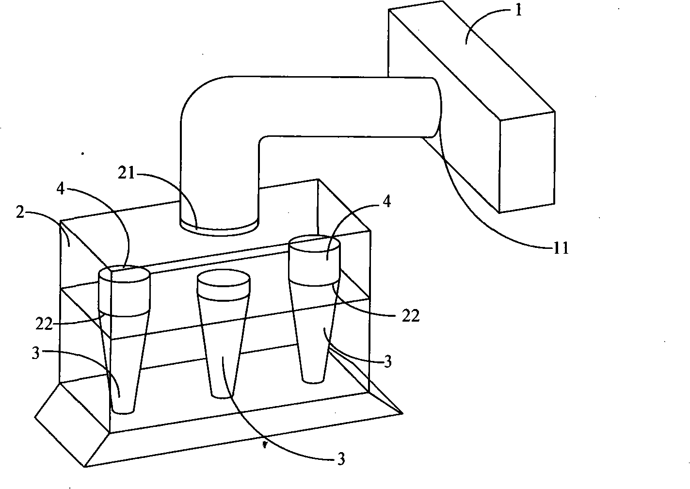
[0059] Such as figure 2 As shown, this embodiment also includes a blower 1 for exhausting gas, the inlet 11 of the blower 1 is connected with the outlet 21 of a cuboid airflow controller 2 . Three circular air intake holes 22 are arranged on the bottom plate of the airflow controller 2 . Each air inlet 22 is directly correspondingly connected with the larger-diameter end of a conical cyclone pipe 3 .

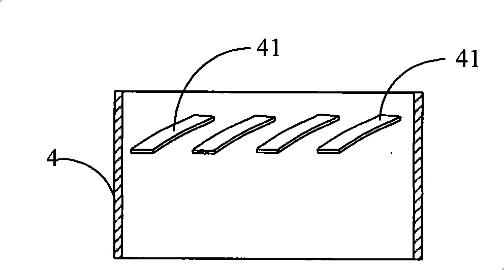
[0060] In the box-shaped body of the air flow controller 2, there are also three flow boosters 4 for controlling the flow velocity and flow direction of the fume gas, and each flow booster 4 communicates with a corresponding air inlet 22 respectively. The flow booster 4 is used to lead out the soot gas in the cyclone tube 3, and the flow rate of the soot gas sent out from the three cyclone tubes 3 can be controlled by setting the corresponding height. Since the outlet 21 of this embodiment is located in the upper middle of the airflow controller 2, in order to balance the thr...

Embodiment 3

[0071] Such as Figure 7 As shown, the difference between this embodiment and the above-mentioned second embodiment is that two inclined partitions 23 are also arranged in the box of the airflow controller 2, and the space in the airflow controller 2 is divided by the partitions 23. Up and down two floors. A hole 231 is opened on the partition plate 23 for connecting with the flow booster 4 .

[0072] In this embodiment, there are altogether four flow enhancers 4, and the number of cyclone tubes 3 is five. The cyclone tube in the middle is not connected with a flow booster, and the remaining four cyclone tubes 3 are respectively connected with a flow booster 4 symmetrically. The flow boosters 4 on the same side have different heights, and their tops are flush with the surface of the partition 23 .

[0073] For the scheme in which the outlet 21 on the airflow controller 2 is arranged at the upper middle, this embodiment has a good oil fume flow distribution control function,...


PUM


Abstract

The invention relates to a oil-smoke purification and discharging device, which comprises a fan used for discharging gas to outside, and the inlet of the fan is connected with the outlet of a box-shaped gas flow controller; a plurality of air inlets are opened on the gas flow controller, and are respectively and correspondingly connected with the larger diameter ends of a plurality of conical cyclone tubes. Through the conical cyclone tubes, the invention can form a stronger air negative-pressure area, and can fast absorb the oil-smoke gas of a large area into the cyclone tubes, then the oil-smoke gas can fast rotate for purification and fast flow for discharging through the effective control of the gas flow controller without any noise, and the oil-smoke gas entering into the cyclone tubes undergoes the purification treatment, thereby enabling the discharged oil-smoke gas not to pollute the surrounding air environment, eliminating the pollution to the kitchen facilities caused by the large amount of oil-smoke during the cooking, and having the capability of fast and silently processing the oil-smoke.

Description

technical field [0001] The invention relates to a device for purifying and discharging oily fume, in particular to a device which firstly purifies the inhaled oily fume gas and then discharges it according to the centrifugal principle and through flow distribution control of the oily fume gas. Background technique [0002] For many years, range hoods of various structures have been widely used in people's daily life as a kind of kitchen equipment. To a certain extent, the environmental pollution caused by oil fumes in the kitchen has been removed for people, but there are some technical defects in the existing range hoods: at first, the range hoods do not effectively purify the smoke gas sucked. The exhausted oil fume will cause certain pollution to the surrounding environment, and sometimes the oily fume gas discharged to the outside will return to the kitchen through the doors and windows along with the air that is pressurized and flowed to the kitchen, especially in summe...

Claims


Application Information

Patent Timeline
Patent Type & Authority Applications(China)
IPC IPC(8): B01D45/16F24C15/20
Inventor 王君
Owner 王君
Why Eureka
Try Eureka