Yarn feeding device for fluid jet loom

A technology of fluid jetting and feeding device, applied in looms, textiles, textiles and papermaking, etc., can solve the problems of detachment of covering parts, loss of bonding function, unimproved, etc., to improve thermal conductivity and heat dissipation effect. High, improve the effect of heat dissipation

Active Publication Date: 2008-09-03
TSUDAKOMA KOGYO KK
View PDF2 Cites 6 Cited by
  • Summary
  • Abstract
  • Description
  • Claims
  • Application Information

AI Technical Summary

Problems solved by technology

[0007] In the past, it was considered that the cause of the above-mentioned problem was the adhesive (adhesive, etc.) used to bond the above-mentioned covering member to the roller or the bonding surface of both, and various changes were tried to them, but the above-mentioned The problem has not improved at all
As a result, the adhesive bonding the roller and the covering member melts and loses its bonding function, resulting in the phenomenon that the covering member is detached from the roller accompanied by the above-mentioned high-speed rotation.
[0009] In particular, the rubber-based materials (urethane rubber, etc.) generally used as the raw material of the covering member of the roller in the weft feeding device are very excellent in preventing relative slippage with the weft yarn and abrasion resistance, but on the other hand, there are High heat and poor heat resistance, so the above problems are prone to occur

Method used


Image

  • Yarn feeding device for fluid jet loom
  • Yarn feeding device for fluid jet loom
  • Yarn feeding device for fluid jet loom

Examples


Embodiment 1

[0048] Here, iron-based materials ( ), aluminum materials ( ), copper-based materials ( ) to form a roller, and the case where the roller is used for the driven roller 4 of the length measuring section 7 in the above-mentioned weft yarn length measuring storage device 2 will be described based on the results of a durability test. In this test, as the driven roller 4, a roller having an outer peripheral diameter of 65 mm and a thickness of the covering member 4b made of polyurethane of 3.5 mm (outer peripheral diameter of the roller 4a: 58 mm) was used. Then, in a water-jet loom with a passing width of 170 cm, in order to shorten the test time, the number of revolutions of the loom was set to 2000 rpm (peripheral speed of the roller: 3400 m / min), which was much higher than the actual level, A test in which the loom was continuously operated for 240 hours was carried out.

[0049] As a result of this test, in the driven roller 4 in which the roller 4a was formed of an ...

Embodiment 2

[0056] In this example, not only the material is different for the roller 4a according to the first example, but also the width of the yarn nip surface 4b1 of the driven roller 4 is considered, and the durability of the case where the width is changed is determined. Explain differently. In addition, as an example of the driven roller 4, a roller having a roller 4a formed of an aluminum-based material is used as an example of the driven roller 4, and the durability of a plurality of rollers having different widths of the yarn nip surface 4b1 on the driven roller 4 is described. the results of the test.

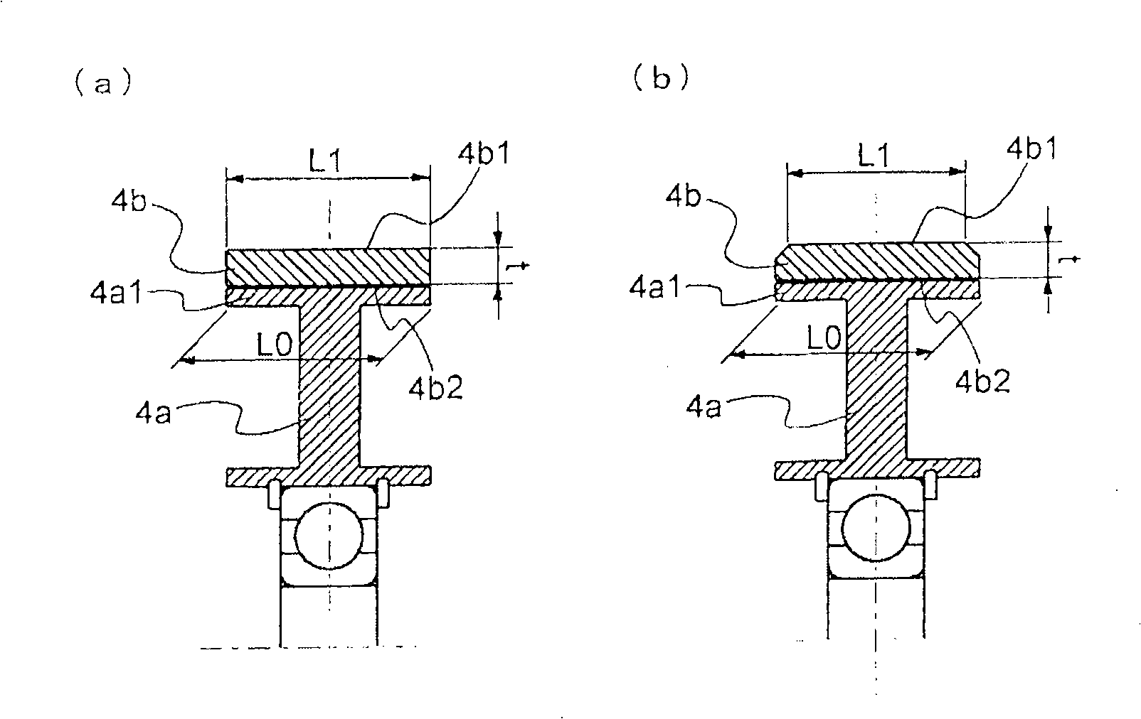
[0057] In the above test, more specifically, the driven roller 4 ( image 3 ) includes a roller 4a with a width L0 of the outer peripheral portion 4a1 of 16.5 mm, and a covering member 4b made of polyurethane rubber, which is formed as an end surface on the side of the roller 4a (=joint surface 4b2 with the roller 4a) The width is equal to the width L0 of the outer peripheral...

Embodiment 3

[0065] In this example, further focusing on the thickness of the covering member 4b on the driven roller 4, the difference in durability when the thickness is changed will be described. In addition, in the following description, the driven roller 4 in which the roller 4a is formed of an aluminum-based material is taken as an example, and the durable The results of the sex test.

[0066] In the above-mentioned test, more specifically, using a roller having a width of 15 mm in the yarn nip surface 4b1 of the driven roller 4 used in the above-mentioned Example 2, the thickness t( image 3 ) was formed to be 5 mm, 4.5 mm, 4 mm, and 3 mm (t = 3.5 mm in the driven rollers 4 of Examples 1 and 2), and the durability test was carried out. In addition, the outer peripheral diameter of each driven roller 4 was set to 65 mm as described in the first embodiment. Furthermore, the loom used for the test and its operating conditions were the same as those in Examples 1 and 2 above.


PUM

PropertyMeasurementUnit
Thicknessaaaaaaaaaa

Abstract

The invention relates to a weft supply device for fluid jet looms, which is arranged on an upstream side position nearer to a weft path than a main nozzle, and uses a pair of rollers rotatably driven by at least one roller as the main structure, wherein the two roller are driven at a circumferential velocity of more than 900m / min. The invention provides a weft supply device capable of operating stably for a long time. The weft supply device is characterized in that at least one of the pair of rollers is composed of a roller wheel made of metal and a coating member made of soft material and stuck to the outer circumference surface of the roller wheel, and the roller wheel is made of a mechanical part material having a thermal conductivity higher than that of ferrum.

Description

technical field [0001] The present invention relates to a weft yarn feeding device of a fluid jet loom, and more particularly to a weft yarn provided at an upstream side of a weft yarn path from a main nozzle and clamped and delivered between a pair of rollers driven by rotation of at least one roller, And the above-mentioned roller is a weft yarn feeding device driven by rotation at a peripheral speed of 900m / min or more. Background technique [0002] As the weft feeding device, there are devices described in Patent Documents 1 and 2, for example. The weft yarn feeding device described in Patent Document 1 (Japanese Unexamined Patent Publication No. 63-21955) is a device that constitutes a part of the weft yarn length measuring storage device, and is arranged upstream of the yarn path of the rotary yarn guide provided in the weft yarn length measuring storage device. A pair of rollers on the side constitutes. In addition, the weft feeding device described in Patent Docume...

Claims


Application Information

Patent Timeline
IPC IPC(8): D03D47/34D03D47/28
Inventor 名木启一仓康弘
Owner TSUDAKOMA KOGYO KK
Why Eureka
Try Eureka