
Microminiaturization co-image face panoramic imagery technique

A panoramic imaging and miniature technology, applied in the field of miniaturized panoramic imaging technology, can solve problems such as poor real-time performance, complex optical structure design, and small image distortion

Inactive Publication Date: 2008-09-03
TIANJIN UNIV
View PDF0 Cites 19 Cited by
  • Summary
  • Abstract
  • Description
  • Claims
  • Application Information

AI Technical Summary

Problems solved by technology

Among them, the rotation stitching method can make the resolution of each image high, and the resolution of the whole panoramic image after stitching is also relatively high, and the image distortion is small, but it needs an accurate rotation mechanism, and the real-time performance is not strong; the fisheye lens method is an ultra-wide-angle The objective lens can obtain images with a large field of view, but the acquired images need to be additionally corrected by the algorithm, and the image distortion is large; the catadioptric panorama method can enable the multi-reflection surface system in the imaging system to obtain a larger field of view, reflection surface and refraction The surface is integrated together, the system is small, the structure is compact, and it is easy to realize miniaturization and integration. The disadvantage is that the optical structure design is complicated

Method used


Image

  • Microminiaturization co-image face panoramic imagery technique
  • Microminiaturization co-image face panoramic imagery technique
  • Microminiaturization co-image face panoramic imagery technique

Examples


Embodiment Construction

[0008] The present invention will be further described below with reference to the accompanying drawings and embodiments.

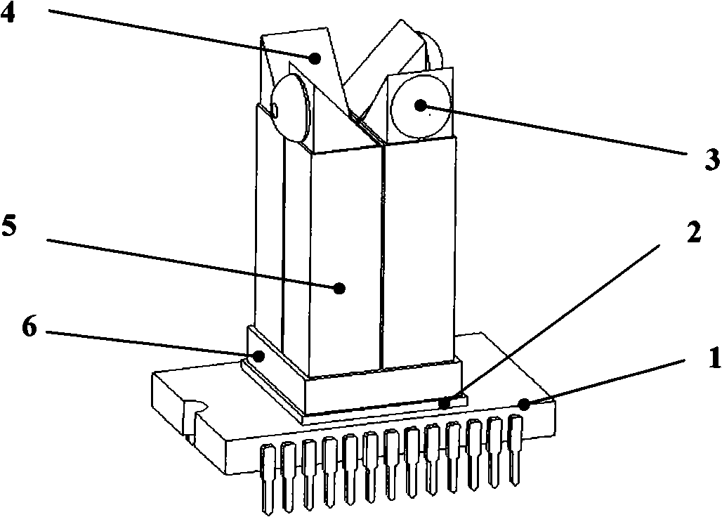
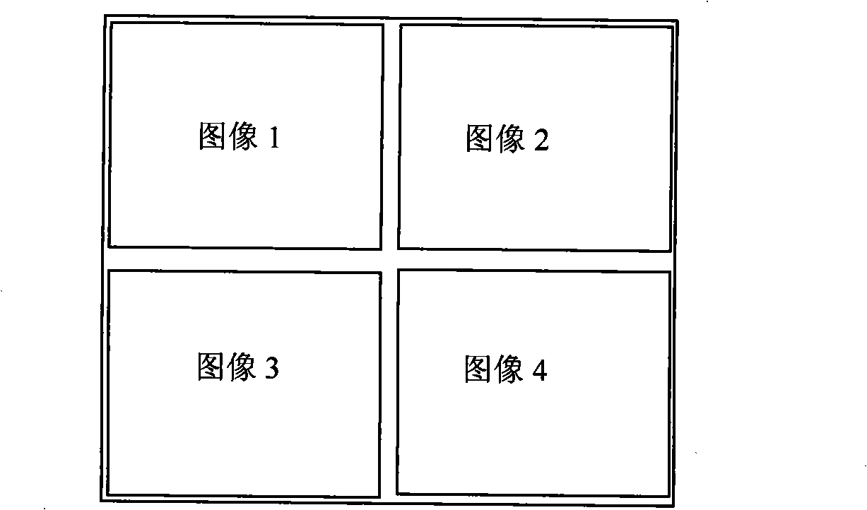
[0009] Such as figure 1 As shown: four imaging optical path frames 5 are adopted, and the focal lengths of the aspherical imaging lenses 3 are the same, that is, f1=f2=f3=f4=12mm. Adjust the direction of the aspheric imaging lens to point to the four directions of front, rear, left and right, and obtain four image plane split common image plane images (such as figure 2 ), using the cylindrical projection model to perform geometric correction on the obtained four image-plane split common-image plane images, and then use the overlapping areas between adjacent images to extract feature information, feature information can be edges and corners, and use the extracted edge The displacement and relative rotation motion relationship between the two images can be determined by feature information such as and corner points, and the splicing of two adjacent images...


PUM


Abstract

A microminiaturized common image surface panorama imaging technique, wherein aspheric imaging lens and corner cube mirror constitute four identical imaging optical path rack and vertically fixed. The number of divided image surfaces by image surface coupler is same to the number of divided image surfaces by aspheric imaging lens and corner cube mirror. The three-dimensional space scene information obtained by aspheric imaging lens and corner cube mirror arrives the image surface coupler by the imaging optical path rack and the imaging surface of imaging device is divided into four same imaging areas in four quadrant using image surface coupler and the four path scene information synchronizes one path to image on the four imaging areas of image surface. Four images on the image surface respectively correspond space scene information on the four direction and are subjected to character matching and image mosaicking based on the overlap area between the two adjacent scene images, in order to obtain a intact space panoramic image. The invention has features of identical linearity, good resolution and real time performance, small aberrance, microminiaturization, particularly suitable for application with higher microminiaturization requirement.

Description

technical field [0001] The invention belongs to the optical imaging technology, and in particular relates to an imaging technology for realizing miniaturized panorama by using image plane segmentation and common image plane imaging methods. technical background [0002] With the development of image sensors and image processing technologies, many fields require real-time panoramic imaging of scenes in all directions in space, such as security monitoring, panoramic target recognition, etc. Rotation stitching, fisheye lens and catadioptric mirror are the main methods of panoramic imaging technology at present. Among them, the rotation stitching method can make the resolution of each image high, and the resolution of the whole panoramic image after stitching is also relatively high, and the image distortion is small, but it needs an accurate rotation mechanism, and the real-time performance is not strong; the fisheye lens method is an ultra-wide-angle The objective lens can ob...

Claims


Application Information

Patent Timeline
IPC IPC(8): G02B17/08G03B37/00G06T5/50
Inventor 王向军刘峰文鹏程张召才
Owner TIANJIN UNIV
Learn More