
Back light module unit having high uniform brilliance

A backlight module, uniform technology, applied in optics, nonlinear optics, mirrors, etc., can solve the problems of difficult manufacturing of light guide plates, troublesome and time-consuming assembly, increased weight and volume, etc., to improve light source efficiency and uniform brightness, improve Variation and variety, easy to process and produce effects

Inactive Publication Date: 2008-09-03
江升晖
View PDF0 Cites 0 Cited by
  • Summary
  • Abstract
  • Description
  • Claims
  • Application Information

AI Technical Summary

Problems solved by technology

[0003] Among them, in order to increase the luminance of the light source of the liquid crystal panel 50, many manufacturers have proposed a method of adding a plurality of prism sheets above the light guide plate 91, but such a method of adding prism sheets will cause troublesome assembly, time-consuming, high cost, and Problems such as increased weight and volume and power loss are obviously not an appropriate solution; moreover, please refer to Taiwan Patent Certificate No. I247142 "Light Guide Plate for Backlight Module", No. M243654 "Backlight System", M266469 No. "Reflector structure of direct-type backlight module to improve reflection and uniform brightness", No. M286939 "Backlight module with high efficiency, high luminance and low board cost" and No. M300824 "Structure improvement of light guide plate", etc., Many manufacturers have proposed to install various light guide structures in the form of concavo-convex configurations on the surface of the light guide plate or reflector to increase the luminance of the light source of the backlight module by improving the uniform refraction of light. However, this changes the surface of the light guide plate or reflector. The shape method will cause difficulties in the manufacture of the light guide plate, increase in weight and volume, and high mold cost. It is still not a good solution

Method used


Image

  • Back light module unit having high uniform brilliance
  • Back light module unit having high uniform brilliance
  • Back light module unit having high uniform brilliance

Examples


Embodiment Construction

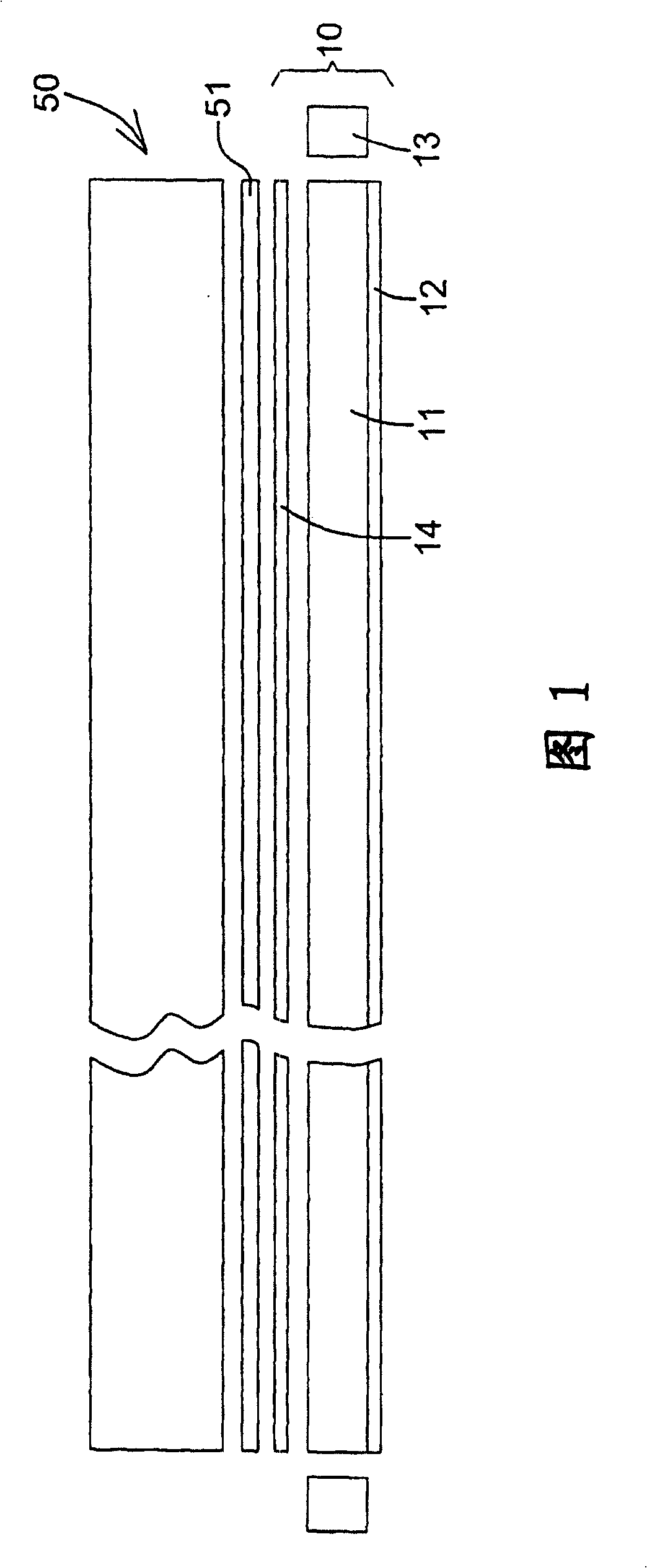
[0035] A preferred embodiment of the backlight module with high uniform luminance provided by the present invention is shown in FIG. Light source devices 13 at the ends of both sides of the light guide plate 11 are constructed, and an optical film 14 can be further arranged above the light guide plate 11; wherein:

[0036] The light guide plate 11 is a light-permeable plate with the equivalent performance of conducting and scattering uniform light;

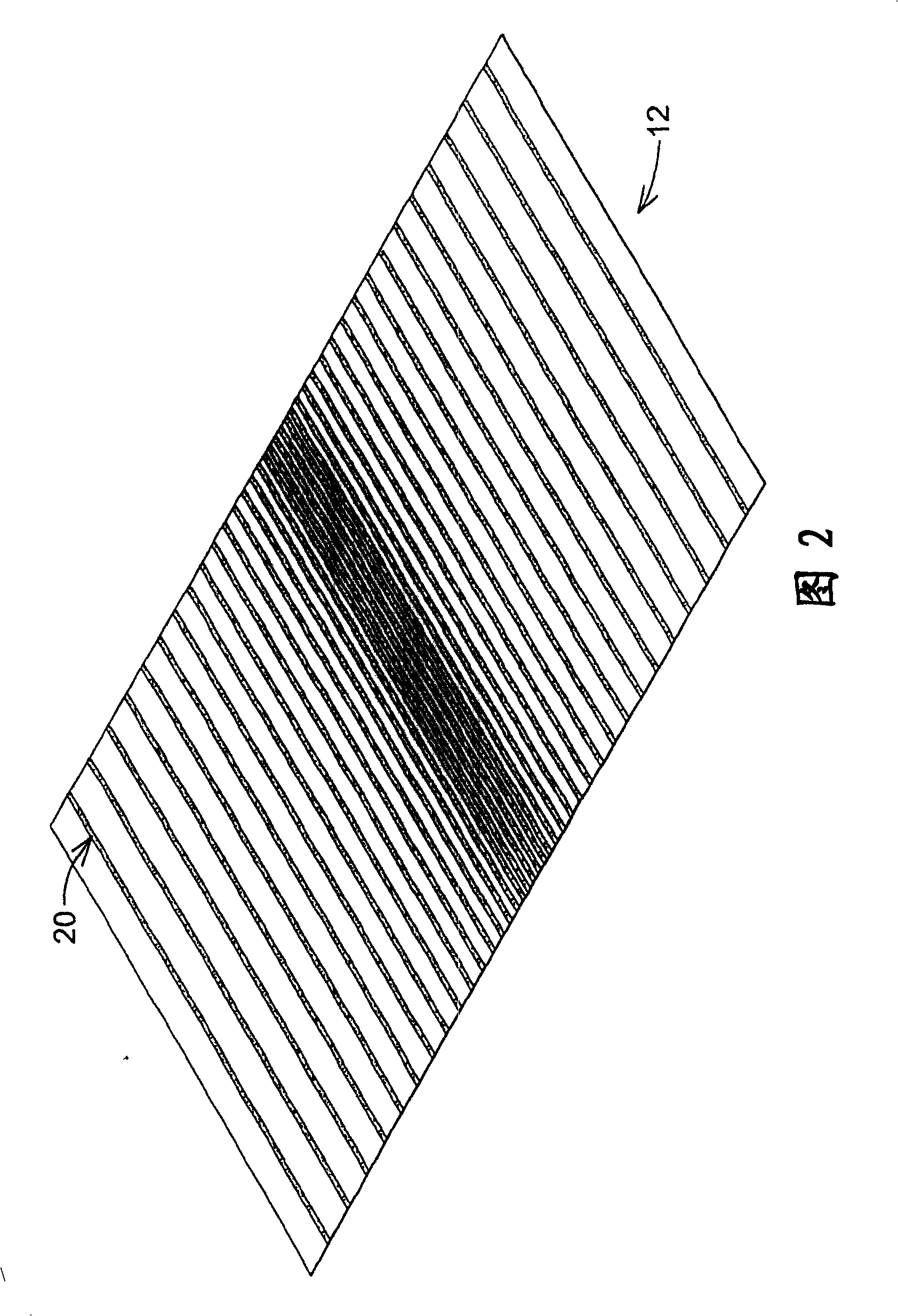
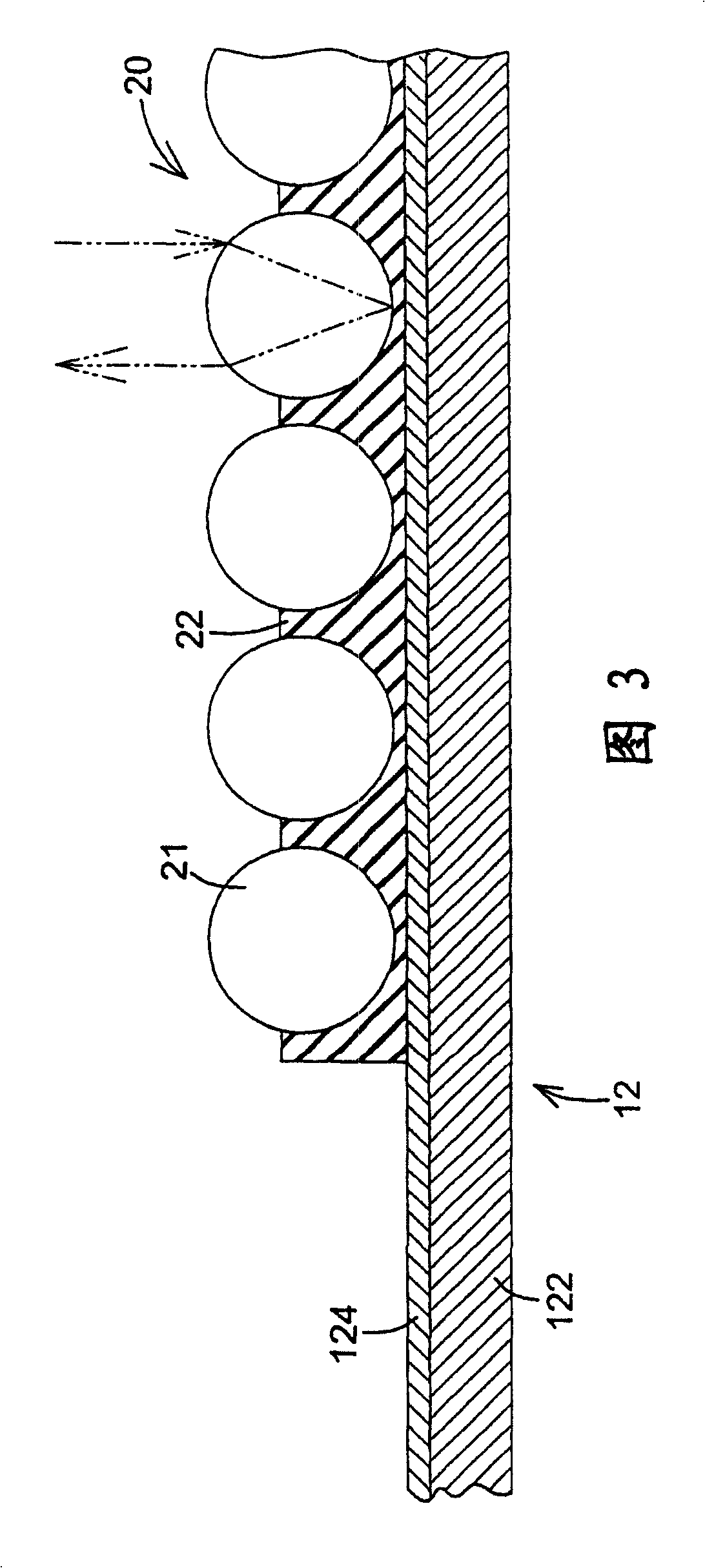
[0037] The reflector 12 is arranged under the light guide plate 11 to reflect the light exposed on the bottom surface of the light guide plate 11 back to the light guide plate 11, as shown in Figure 2 and Figure 3, the reflector 12 is provided with a rigid or flexible The base material 122 is coated with a reflective layer 124 made of diffuse reflective material on the surface of the base material 122 facing the direction of the light guide plate 11, and according to the needs of product design and the position of each light sourc...


PUM


Abstract

The invention provides a backlight module with high uniform brightness, in order to solve the problem that the present backlight module has not enough brightness and uniformity. A plurality of reflection bead layers are disposed on the reflection slice surface below a guide light plate. A plurality of granular reflection beads are disposed on the surface of each reflection bead layer. The invention can effectively and uniformly reflects the light from the bottom of the guide light plate to the guide light plate using condensation, intensifying film and reflection function of each flection bead and effectively increases the source efficiency and uniform brightness of backlight module in simple way.

Description

technical field [0001] The invention relates to a backlight module applied to a liquid crystal panel, in particular to a design of a reflection plate of the backlight module capable of improving reflection efficiency and uniform luminance. Background technique [0002] Please refer to FIG. 4, the backlight module 90 generally used in the liquid crystal panel 50 mainly includes a light guide plate (LGP) 91, a reflector 92 located under the light guide plate 91, and a reflector 92 located on the side of the light guide plate 91. The light source device 93 at the top of the light guide plate 91, and an optical film (Prism sheet) 94 above the light guide plate 91; in this way, after the light source provided by the light source device 93 is incident on the light guide plate 91, it passes through the conduction and reflection sheet 92 of the light guide plate 91 reflection, refract light to the liquid crystal panel 50 above the backlight module 90 to provide the light required by...

Claims


Application Information

Patent Timeline
Patent Type & Authority Applications(China)
IPC IPC(8): G02F1/1335G02B5/08
Inventor 江升晖
Owner 江升晖
Learn More