Horizontal radiation type electrolysis method and device

A technology of electrolysis device and electrolysis method, which is applied in the direction of electrolysis process, electrolysis components, chemical instruments and methods, etc. It can solve the problems of calcium accumulation, space occupation, and inability to adjust the electrolytic tank, and achieve the solution of accelerating calcium accumulation, reducing costs, and shunting easy effect

Inactive Publication Date: 2010-05-26
徐文星
View PDF5 Cites 1 Cited by
  • Summary
  • Abstract
  • Description
  • Claims
  • Application Information

AI Technical Summary

Problems solved by technology

[0003] 1. In vertical electrolyzers, most acid and alkaline water outlets are designed to take water from above, which leads to residual water remaining in the electrolyzer after electrolysis, and an additional residual water discharge device is required, which leads to increased costs ; and if no residual water discharge device is installed, the residual water will breed bacteria and cause calcium ion precipitation, which will accelerate calcium accumulation in the electrolytic cell; The standard value of the redox potential cannot be reached
[0004] 2. In the vertical electrolytic cell, the unit area of ​​the water inlet and the water outlet are equal, and the electrolysis current is also similar. If the electrode spacing of the water outlet is to be increased, the resistance of the water outlet will be relatively increased, so the current at the water outlet will also be reduced. The total electrolysis current, thereby relatively reducing the range of the neutral water layer, makes it difficult to divide the anion and cation laminar flow
[0005] 3. In the vertical electrolyzer, the unit area of ​​the water inlet and the water outlet are equal, and the flow velocity entering the electrode plate inlet is equal to the flow velocity leaving the electrode plate outlet, which cannot slow down the flow velocity at the diversion point, and it is relatively easy to generate turbulence.
[0006] 4. The vertical electrolyzer is generally designed with the water inlet on the bottom and the water outlet on the top, so it needs a certain water pressure to work. For the case of low water pressure, such as the water storage tank of the water dispenser, it must be pressurized by the pumping motor. , otherwise it cannot be applied
[0007] 5. Most of the vertical electrolytic cells are locked by a large number of screws, which makes the disassembly and assembly of the cathode and anode electrode plates extremely inconvenient, and also increases the cost
[0008] 6. The vertical electrolytic cell cannot be installed in the flat space below the water storage tank of the water dispenser. If the vertical electrolytic cell must be installed inside the water dispenser, it will take up more space; in addition, an external pipeline must be connected to guide the water The water inlet of the electrolyzer, after electrolysis, needs to use pipelines to export acidic water and alkaline water and connect them to the water outlet of the water dispenser, which undoubtedly increases the complexity of assembly and also increases the cost; Calcium builds up in the water outlet pipe, which needs to be cleaned regularly
[0009] 7. The electrode spacing of the vertical electrolyzer is fixed, and it is impossible to adjust the electrode spacing appropriately for the soft water area or the hard water area, so its scope of application is limited; the electrode spacing of the soft water area is generally designed to be smaller than that of the hard water area, and the hard water area is reversed. The electrode spacing design is slightly larger than the soft water area, so there are certain limitations in the fixed electrode spacing design

Method used


Image

  • Horizontal radiation type electrolysis method and device
  • Horizontal radiation type electrolysis method and device
  • Horizontal radiation type electrolysis method and device

Examples


specific Embodiment

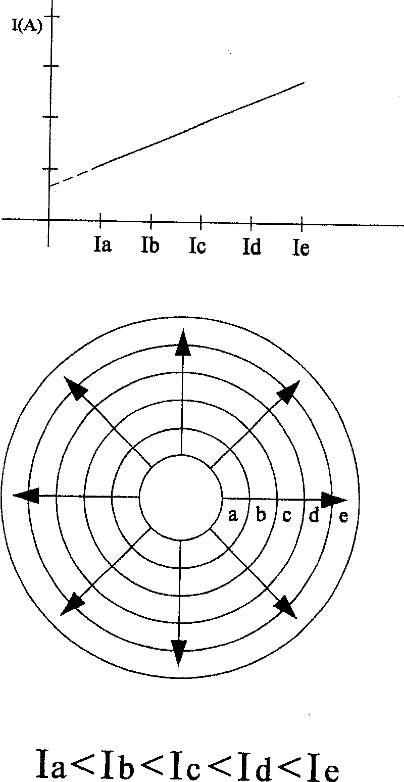
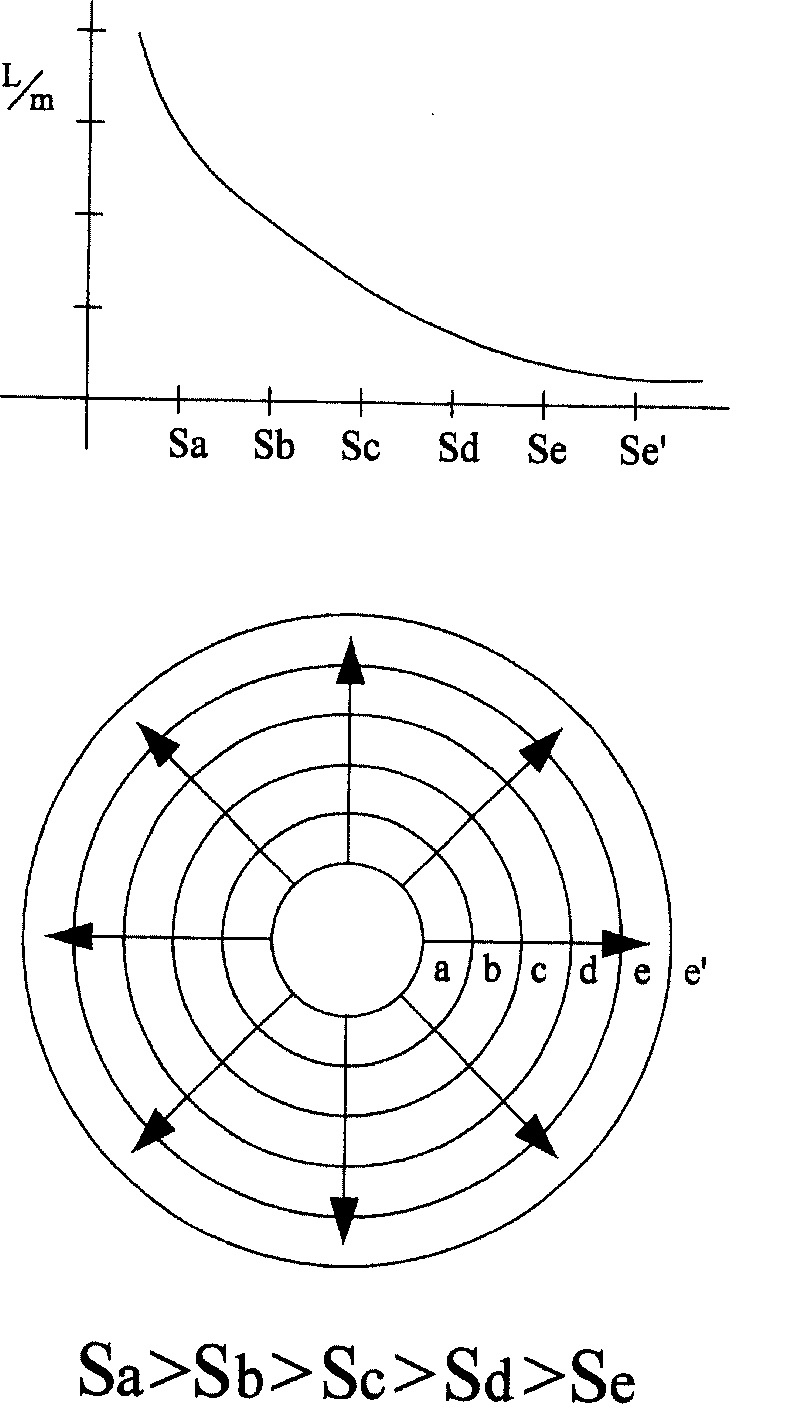
[0071] A horizontal radiation electrolysis method is characterized in that the raw water is introduced from the center of the electrode plate and radiated out horizontally outward, so that the flow rate of the incoming water can be slowed down during electrolysis and the best electrolysis efficiency can be obtained.

[0072] According to the above-mentioned horizontal radiation electrolysis method of the present invention, the produced horizontal radiation electrolysis device includes at least the following seven embodiments:

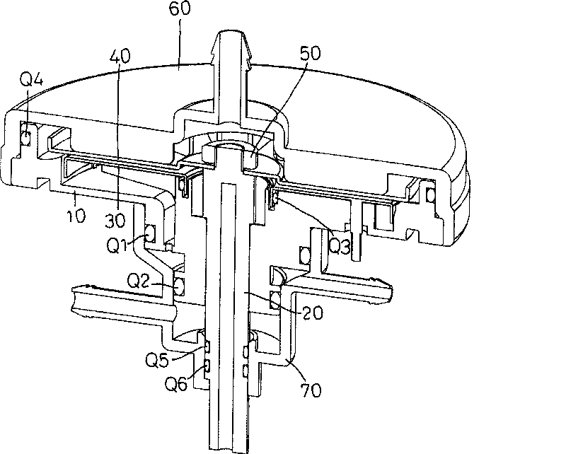
[0073] Regarding the first embodiment of the present invention, please refer to image 3 , 4 , 5, image 3 , 4 It is a three-dimensional combined cross-sectional view and a three-dimensional exploded schematic view of the first embodiment of the present invention. Figure 5 It is a schematic diagram of the cross-sectional combination of the first embodiment of the present invention. The electrolysis device includes a base body 10 , a conductor 20 , ...


PUM


Abstract

The invention relates to a horizontal radial electrolysis method and a horizontal radial electrolysis device. The device comprises a base body, a first battery lead plate, a second battery lead plate,a cover body and a water connection; the first battery lead plate and the second battery lead plate are arranged between the base body and the cover body and the water connection is arranged on the base body; wherein, the first battery lead plate and the second battery lead plate are arranged on horizontal opposite surfaces of the cover plate and the base body; the center of one battery lead plate of the first battery lead plate and the second battery lead plate is provided with a water inlet; raw water is directly led into the water inlet and flows out by means of horizontal radial diffusion; under the condition of electrolysis, an acid water layer and an alkaline water layer are respectively formed on horizontal sides of the first battery lead plate and the second battery lead plate; the cover body and the base body opposite to the battery lead plates are provided with a first effluent flow path and a second effluent flow path, thereby acid water and alkaline water are shunted and led out.

Description

technical field [0001] The invention relates to a technical horizontal radiation electrolysis method and device applied to the laminar flow of anion and cation in an electrolytic cell of a water electrolysis machine to stabilize the water flow. Background technique [0002] Currently, the conventional and commonly used vertical electrolyzers have the following problems: [0003] 1. In the vertical electrolytic cell, most of the acid and alkaline water outlets are designed to take water from above, which leads to residual water remaining in the electrolytic cell after electrolysis, and an additional residual water discharge device needs to be installed, which leads to increased costs. If the residual water discharge device is not installed, the residual water will breed bacteria and cause calcium ion precipitation, which will accelerate the accumulation of calcium in the electrolysis cell; The standard value of redox potential could not be reached. [0004] 2. In the vertic...

Claims


Application Information

Patent Timeline
Patent Type & Authority Patents(China)
IPC IPC(8): C25B9/00C02F1/461
Inventor 徐文星
Owner 徐文星
Why Eureka
Try Eureka