
Gas spring environmental simulated fatigue-testing machine

A fatigue testing machine and environmental simulation technology, applied in the field of gas spring environmental simulation fatigue testing machine, can solve the problems of long heating and cooling time, affecting service life, high energy consumption, and achieving small box volume, good sealing effect, and cooling energy. low consumption effect

Active Publication Date: 2008-09-10
施与秋
View PDF1 Cites 27 Cited by
  • Summary
  • Abstract
  • Description
  • Claims
  • Application Information

AI Technical Summary

Problems solved by technology

In addition to the power mechanism, the simulated fatigue testing machine with the above structure, the mechanical transmission mechanism, the simulated back door and the gas spring are all placed in a large environmental test chamber. Since the mechanical transmission mechanism adopts a chain transmission mechanism, the alternating ambient temperature also affects the chain transmission. mechanism and the service life of the action mechanism such as the analog back door
On the other hand, since the test bench needs to be placed in a large-scale environmental test chamber, if the temperature in the environmental test chamber is to reach the high and low alternating temperature set by the test, the heating and cooling time in the test chamber will be longer, so the energy consumption will be higher. Therefore, there is currently no machine that is convenient for simulating the fatigue test of the gas spring under test at alternating ambient temperatures.

Method used


Image

  • Gas spring environmental simulated fatigue-testing machine
  • Gas spring environmental simulated fatigue-testing machine
  • Gas spring environmental simulated fatigue-testing machine

Examples


Embodiment Construction

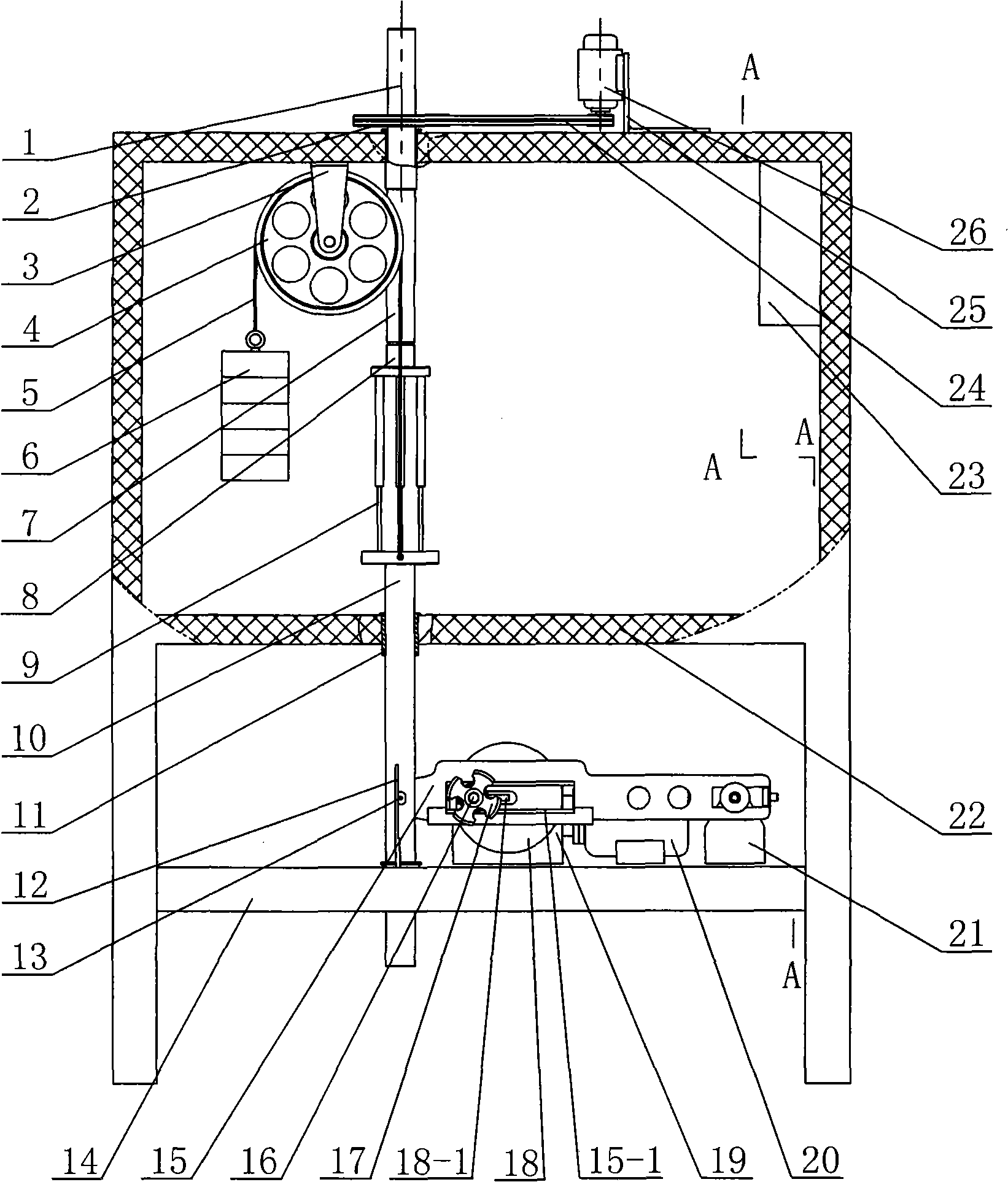
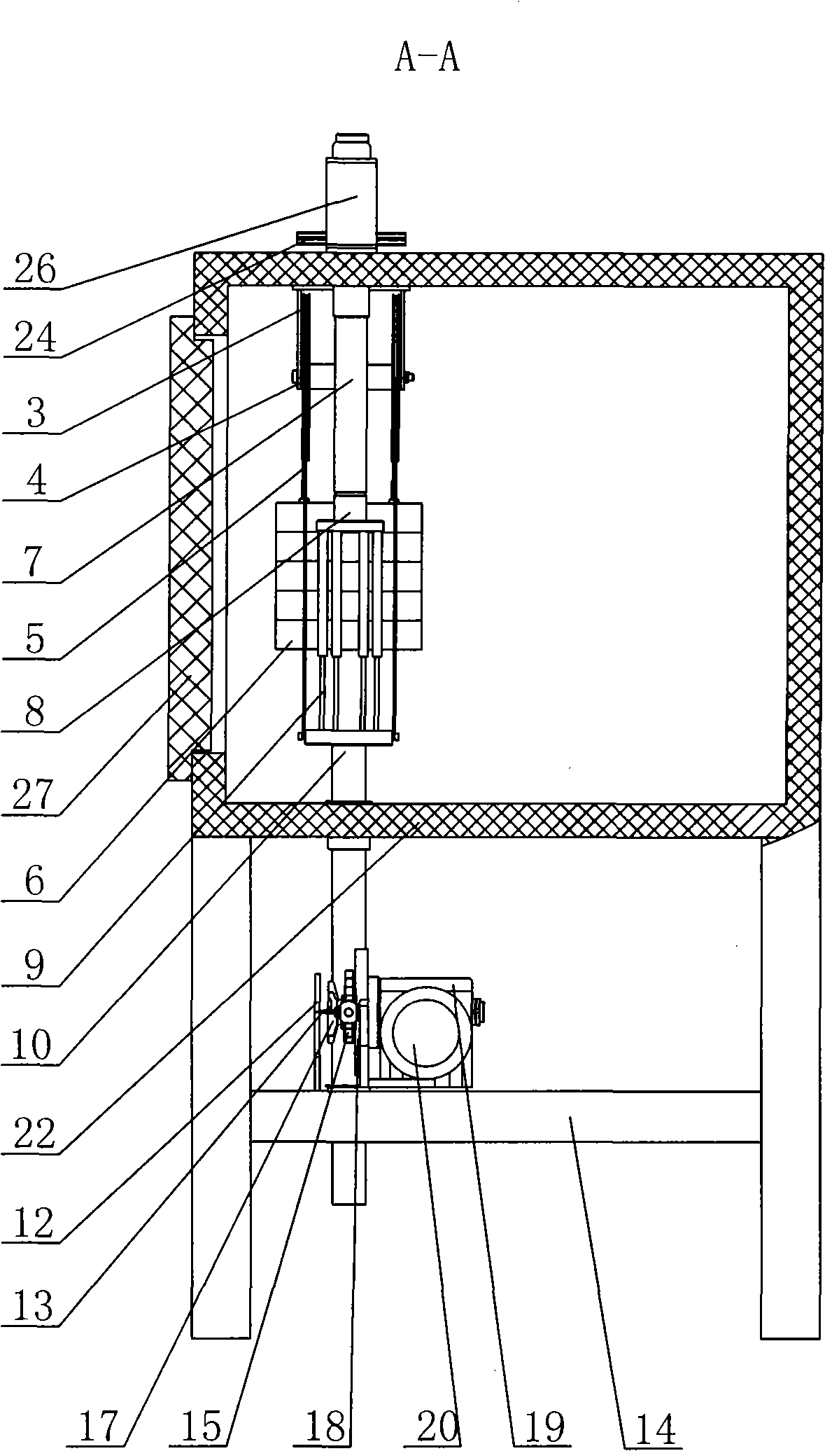
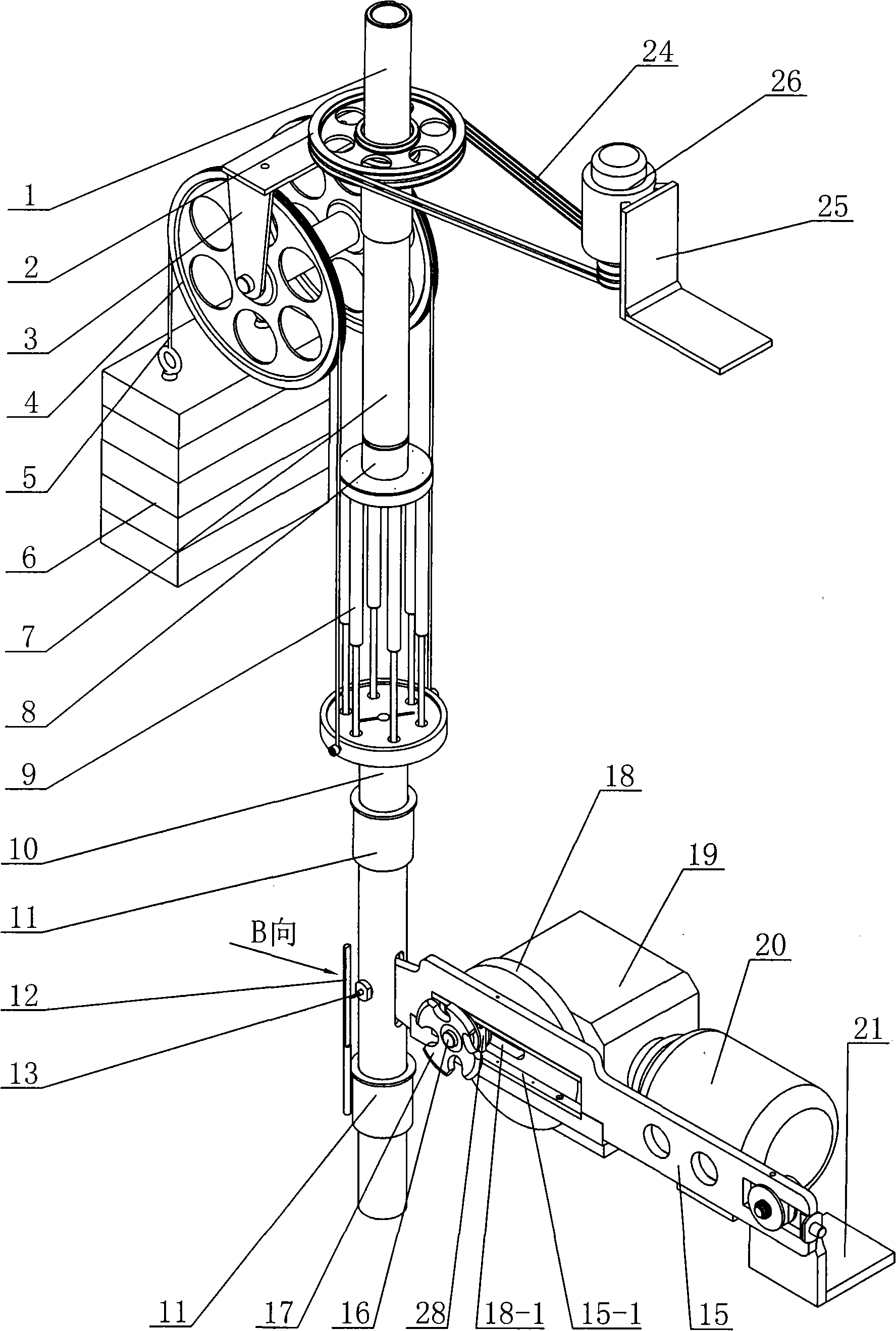
[0015] See Figure 1~3 As shown, the gas spring environmental simulation fatigue testing machine of the present invention includes a frame 14 , a box assembly, a mechanical transmission device, a counterweight device, a hanging plate 8 and a transmission shaft 10 . See figure 1 Shown, the box body assembly of the present invention is made of the box body 22 of heat preservation and the box door 27 that is installed on the box body 22, and box body assembly is fixed on the frame 14, and heating and cooling device 23 is installed in the box body 22, or The heating and cooling device 23 is installed outside the box body 22, and the box body 22 has a vent, and the simulated ambient temperature of the gas spring under test in the box body 22 is controlled by controlling the heating and cooling device 23.

[0016] See Figure 1~3 As shown, the mechanical transmission device of the present invention is installed on the frame 14 and is positioned at the outside of the casing 22, and...


PUM


Abstract

The invention relates to an air spring environment simulation fatigue testing machine, comprising a frame, a box body component, a mechanical transmission device, a counterweight device, a hoisting disc and a transmission shaft; the box body component consists of a box body and a box door with heat preservation function; the mechanical transmission device is arranged on the frame and is positioned outside the box body; the motor of the mechanical transmission device is connected with a rotation disc by a reducer; the swing shaft which is arranged on the rotation disc is connected with a sliding block which is arranged in the guide trough of a swing rod; one end of the swing rod is articulated on the supporter of the swing rod; the transmission shaft with a tray is arranged inside the box body; the transmission shaft passes through the box body and is articulated with the other end of the swing rod; the hoisting disc is connected inside the box body and is corresponding to the transmission shaft; the counterweight bracket of the counterweight device is fixed on the top inside the box body; two disc bodies are coaxially arranged on the counterweight bracket; two ends of the steel cables which are arranged in two disc body ring-shaped trough are respectively connected on the counterweight block and the transmission shaft. The air spring environment simulation fatigue testing machine has reasonable structure, does not affect the actuating unit and the transmission mechanism of the testing machine or the service life of the transmission mechanism, and has the advantages of convenient operation and low energy loss.

Description

technical field [0001] The invention relates to a gas spring environment simulation fatigue testing machine, which belongs to the technical field of gas springs. Background technique [0002] The gas spring simulation fatigue testing machine is to simulate the working state of the gas spring, and then test whether the gas spring under test can meet the design requirements. Conventional simulated fatigue testing machines can only perform simulated fatigue tests at room temperature. Since they cannot test the working environment of real gas springs, they cannot ensure the reliability and durability of gas springs under different temperature and environmental conditions. The "compressible gas spring durability test bench" disclosed by CN2615658Y is a test bench placed in a large-scale environmental test chamber, which is composed of an adjustable base, a column, a test piece support and a simulated back door, etc., wherein the column is fixed Welded on the base, the specimen b...

Claims


Application Information

Patent Timeline
IPC IPC(8): G01M13/00
Inventor 施与秋张国平
Owner 施与秋
Learn More