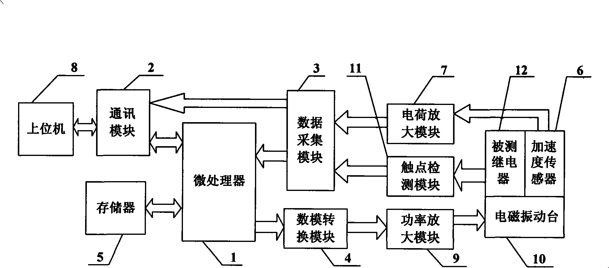
Electromagnetic relay dynamic environmental test system
A technology of electromagnetic relay and mechanical environment, applied in the direction of circuit breaker testing, instruments, etc., can solve the problem that vibration condition control information and contact state monitoring information cannot be obtained at the same time, and achieve the effect of good control accuracy
- Summary
- Abstract
- Description
- Claims
- Application Information
AI Technical Summary
Problems solved by technology
Method used
Image
Examples
specific Embodiment approach 1
[0008] Specific implementation mode one: combine figure 1 Description of this embodiment, this embodiment consists of a microprocessor 1, a communication module 2, a data acquisition module 3, a digital-to-analog conversion module 4, a memory 5, an acceleration sensor 6, a charge amplification module 7, a host computer 8, a power amplification module 9, The electromagnetic vibrating table 10 and the contact monitoring module 11 are composed; the microprocessor 1 is connected to the memory 5 through the address bus and the data bus, and the data output end of the microprocessor 1 is connected to the data input end of the digital-to-analog conversion module 4, and the digital-to-analog conversion module The analog signal output end of 4 is connected to the analog signal input end of the power amplification module 9, the output end of the power amplification module 9 is connected to the drive input end of the electromagnetic vibrating table 10, and the measured relay 12 and the ac...
specific Embodiment approach 2
[0009] Specific implementation mode two: combination figure 2 Describe this embodiment, the difference between this embodiment and specific embodiment 1 is that the contact monitoring module 11 is composed of a first operational amplifier L1, a second operational amplifier L2, a first resistor R1 to a ninth resistor R9, and a first capacitor C1 to a second capacitor. Composed of four capacitors C4; the first electric shock signal output end of the relay is connected to one end of the fifth resistor R5, one end of the seventh resistor R7 and pin 3 of the first operational amplifier L1, and the other end of the fifth resistor R5 is connected to a 5V power supply, the relay first The second electric shock signal output terminal is connected to the other end of the seventh resistor R7 and grounded, the pin 4 of the first operational amplifier L1 is connected to one end of the eighth resistor R8 and one end of the third capacitor C3, and the other end of the eighth resistor R8 is c...
PUM
 Abstract
Description
Claims
Application Information
 - R&D
- Intellectual Property
- Life Sciences
- Materials
- Tech Scout
- Unparalleled Data Quality
- Higher Quality Content
- 60% Fewer Hallucinations
Browse by: Latest US Patents, China's latest patents, Technical Efficacy Thesaurus, Application Domain, Technology Topic, Popular Technical Reports.
© 2025 PatSnap. All rights reserved.Legal|Privacy policy|Modern Slavery Act Transparency Statement|Sitemap|About US| Contact US: help@patsnap.com


