
Draught fan

A technology for induced draft fans and fans, applied in mechanical equipment, machines/engines, liquid fuel engines, etc., can solve the problems of putting into use, unattainable noise pollution, increasing noise pollution, etc., reducing noise and friction. , The effect of avoiding industrial noise pollution

Inactive Publication Date: 2008-09-17
倪如宝
View PDF0 Cites 5 Cited by
  • Summary
  • Abstract
  • Description
  • Claims
  • Application Information

AI Technical Summary

Problems solved by technology

[0002] The induced draft fan in the prior art, with the increase of the induced draft power, the noise pollution it produces is also increasing, even as high as 60-80 decibels
Even if the induced draft fan with higher power can be produced under the mechanical structure sound, it cannot be put into use if the control of noise pollution cannot meet the national environmental protection standard

Method used


Image

  • Draught fan
  • Draught fan
  • Draught fan

Examples


Embodiment Construction

[0016] The specific embodiment of the present invention is described below:

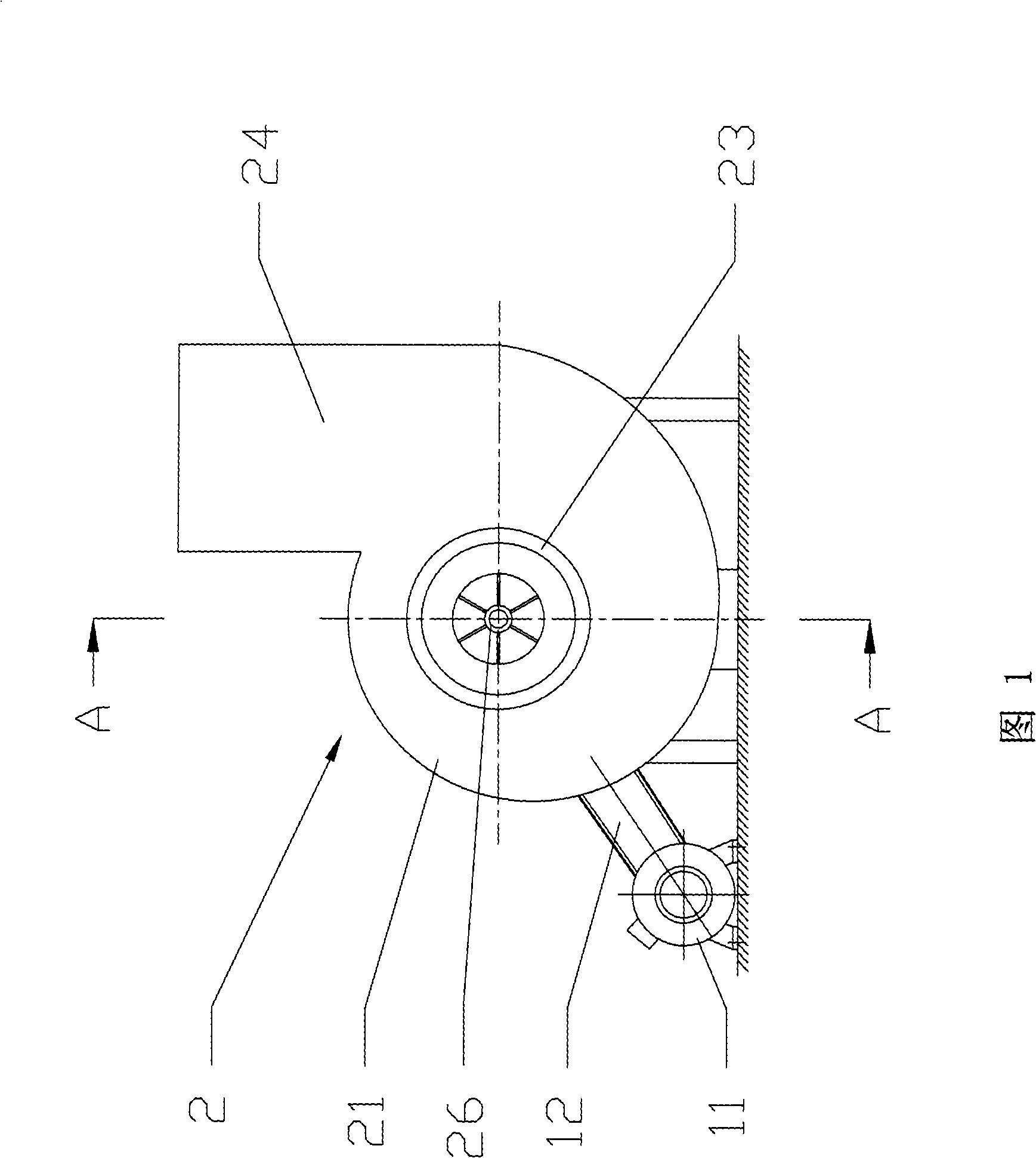
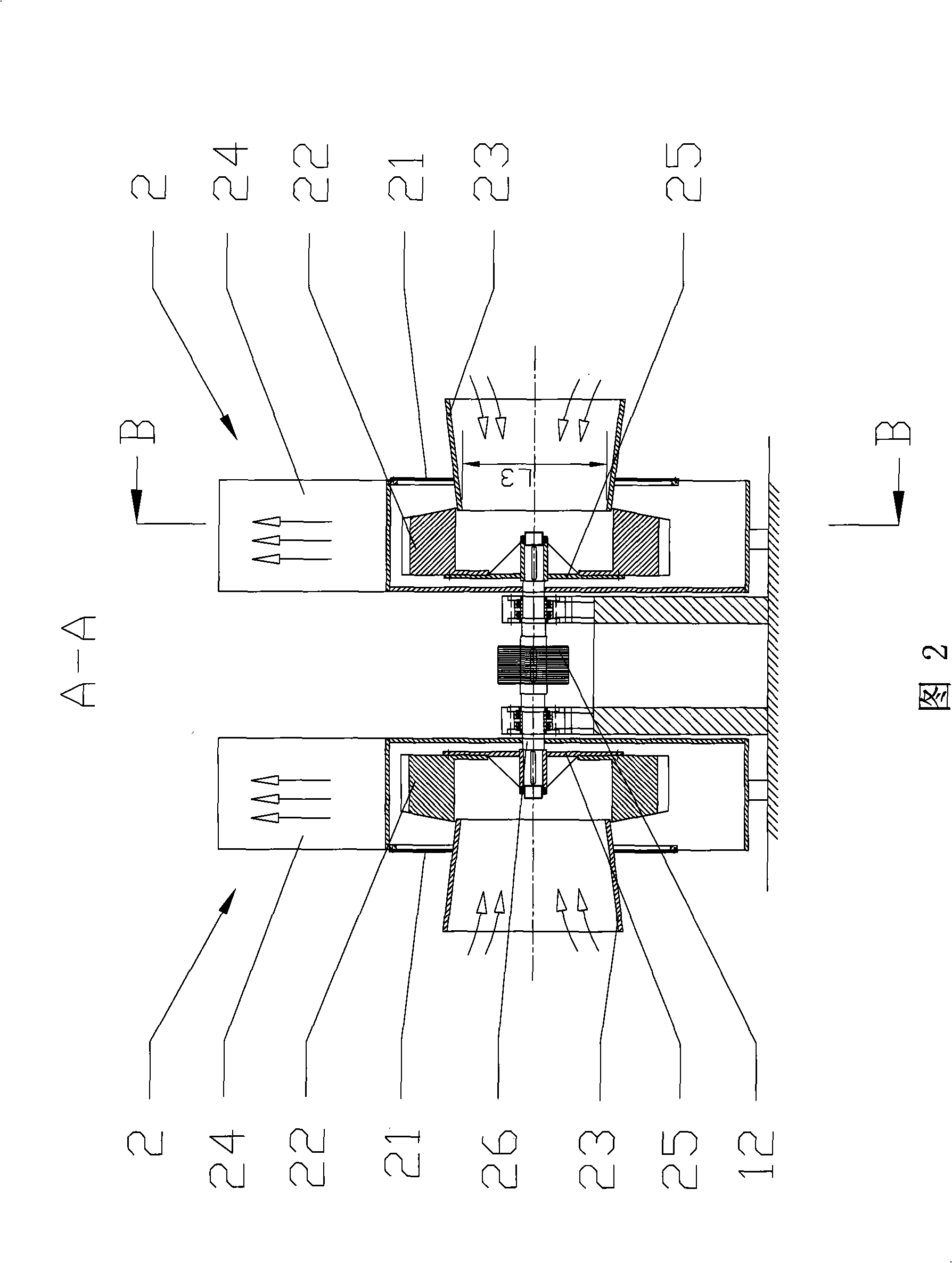
[0017] As shown in FIG. 2 , an induced draft fan according to the present invention includes a pair of fan main bodies 2 arranged symmetrically on both sides of a motor 11 . Each fan main body 2 includes a fan casing 21 and a group of impellers 22 arranged in the fan casing 21 . The two sets of impellers 22 in the pair of blower main bodies 2 are respectively mounted on the two ends of the horizontal double-headed main shaft 26 , so that they can be driven by the motor 1 to rotate around the shaft in interlocking manner.

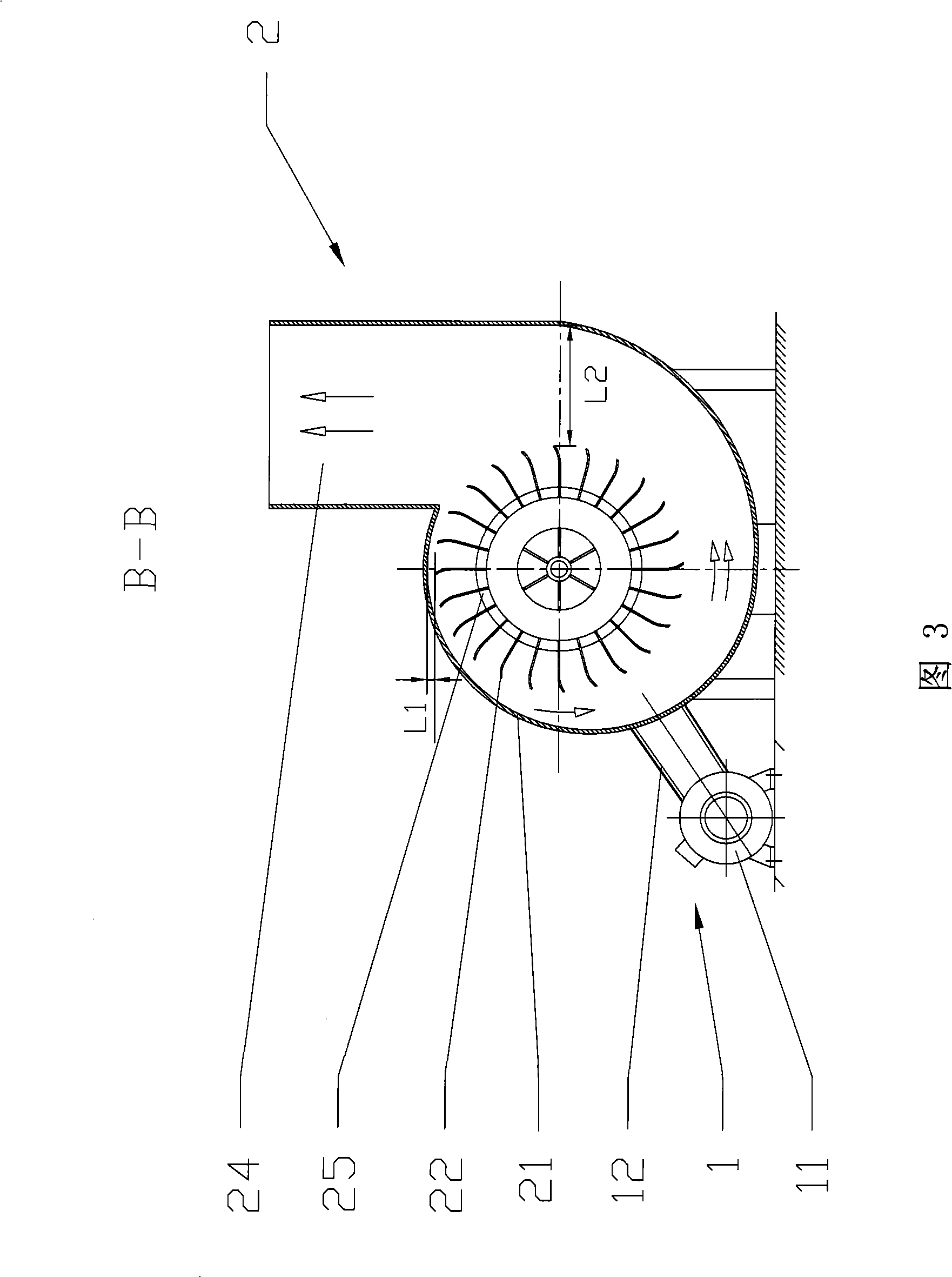
[0018] As shown in FIG. 1 , the cross-sectional shape of the fan housing 21 perpendicular to the axial direction is a logarithmic spiral.

[0019] As shown in accompanying drawings 1 and 2 , on one side of the fan housing 21 , a trumpet-shaped air inlet pipe 23 is provided coaxially with the impeller 22 . On the cylindrical side wall of the fan casing 21 , an air outlet pipe 24 i...


PUM


Abstract

The invention relates to a draft fan including a fan body which is driven by power equipment and comprises a fan shell and an impeller which is arranged in the fan shell and can be driven by the power equipment to rotate along the horizontal axis. An air intake is arranged on one side of the fan shell along the axis and an air outtake is arranged on the fan shell along the direction tangent to the rotation track of the outer edge of the impeller. The fan shell cross section which is vertical to the axis is in the shape of logarithmic spiral, and the rotation track of the outer edge of the impeller is a circle. The longest distance between the circle and the fan shell is 0.7 to 1 time of the radius of the circle, and shortest distance between the circle and the fan shell is 0.1 to 1.1cm. The draft fan reduces the friction between the air and the metal shell and the noise by increasing the distance between the fan shell and the impeller. The increase of the fan cavity size will lead to the increase of the draught flow rate, thus improving the efficiency and achieving the energy saving purpose.

Description

technical field [0001] The invention relates to an induced draft fan, more specifically, to a centrifugal large displacement induced draft fan. Background technique [0002] In the induced draft fan in the prior art, with the increase of the induced draft power, the noise pollution produced by it also increases continuously, even as high as 60-80 decibels. Even if a more powerful induced draft fan can be produced in the mechanical structure acoustics, it cannot be put into use if the control of noise pollution cannot meet the national environmental protection standards. [0003] The noise of the induced draft fan mainly comes from the vibration and friction caused by the collision between the high-speed rotating air and the metal equipment in the induced draft fan. At the same time, the mechanical vibration and friction of the high-speed rotating mechanical equipment are also the source of the noise. [0004] Therefore how to reduce the noise becomes the key to increasing t...

Claims


Application Information

Patent Timeline
IPC IPC(8): F04D29/42F04D29/28F04D29/66
Inventor 倪如宝姬高生
Owner 倪如宝
Learn More