Digital photoelasticity full field shear stress automatic determination method

A technology for automatically determining and shearing stress, applied in electrical digital data processing, special data processing applications, material analysis through optical means, etc., can solve problems such as not calculating shear stress

Inactive Publication Date: 2008-09-17
DALIAN UNIV OF TECH
View PDF0 Cites 11 Cited by
  • Summary
  • Abstract
  • Description
  • Claims
  • Application Information

AI Technical Summary

Problems solved by technology

The more eye-catching work is based on the four-step color phase shift method based on the white light plane polarization field, which basically completes the judgment of the principal stress direction with only four images, but does not calculate the shear stress

Method used


Image

  • Digital photoelasticity full field shear stress automatic determination method
  • Digital photoelasticity full field shear stress automatic determination method
  • Digital photoelasticity full field shear stress automatic determination method

Examples


Embodiment 1

[0053] Embodiment 1: Automatic calculation of full-field shear stress of epoxy resin radial compression disc

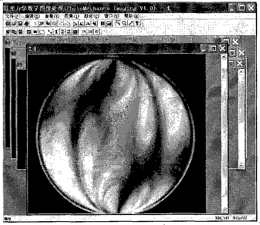
[0054] figure 2 In order to actually collect 4 images of epoxy resin diametrically compressed disks required by the four-step color phase shift method, the diametrically compressed disks have a diameter of 60mm, a thickness of 8mm, and a material stripe value of 12.4N / (mm bar). The radial compression loading method is adopted, and the load is 60kg. According to the measurement method mentioned above, the detection process is:

[0055] (1) Place the measured anti-diameter compression disc in a photoelasticity instrument to apply a load;

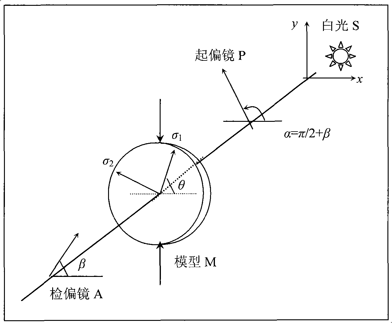
[0056] (2) Adjust the light field to the orthogonal plane polarization field under the incidence of white light. When the analysis mirror and polarizer are synchronously rotated to 0, π / 8, π / 4 and 3π / 8, four phase-shifted images are collected respectively, see figure 2 ;

[0057] (3) The first principal stress direction (-π / 2, π / 2...

Embodiment 2

[0061] Example 2: Automatic calculation of full-field shear stress of epoxy resin three-point bending beam

[0062] Figure 9 In order to actually collect 4 epoxy resin three-point bending beam images required by the four-step color phase shift method, the size of the epoxy resin beam is 180mm×32mm×6mm, and the material stripe value is 11.12N / (mm bar). The three-point bending loading method is adopted, the supporting span is 120mm, and the load is 20kg. According to the measurement method mentioned above, the detection process is:

[0063] (1) Place the measured three-point bending beam in a photoelasticity instrument to apply a load;

[0064] (2) Adjust the light field to the orthogonal plane polarization field under the incidence of white light. When the analysis mirror and polarizer are synchronously rotated to 0, π / 8, π / 4 and 3π / 8, four phase-shifted images are collected respectively, see Figure 9 ;

[0065] (3) The first principal stress direction (-π / 2, π / 2] phase d...


PUM

PropertyMeasurementUnit
diameteraaaaaaaaaa
thicknessaaaaaaaaaa

Abstract

The invention provides a full-court shearing stress automatic determining method in digital photoelasticity, belonging to a photoelectricity non-destructive test field, comprising: laying the detected photoelasticity body in a photoelastical gauge to apply load, and adjusting the optical field being orthogonal plane polarization field under the white light incidence and respectively collecting four phase shift images when an analyser and a polarizer synchronistically rotate to 0, Pi/8, Pi/4 and 3Pi/8; obtaining the phase diagram of first major principal stress (-Pi/2,Pi/2) using four step color phase-shift method; adjusting the optical field being orthogonal circular polarization field user homogeneous light incidence and collecting six phase shift images when the analyser and the second 1/4 wave plate respectively rotate to (Pi/4,0), (3Pi/4,0), (0,0), (Pi/4,Pi/4), (Pi/2,Pi/2) and (3Pi/4,3Pi/4); combining the phase diagram of first major principal stress and using the improved six phase shift method to obtain isochromatic line packing phase diagram without 'distortion' and performing packing and calculating the full-court shearing stress. The full-court shearing stress can be automatically calculated and the work efficiency is increased and the complicated work of manually data collecting and processing is prevented.

Description

technical field [0001] The invention belongs to the technical field of photoelectric non-destructive testing, and relates to a method for automatically determining full-field shear stress in digital photoelasticity. Background technique [0002] The method of combining photoelasticity with computer image processing technology to automatically collect photoelastic data and analyze stress is called digital photoelasticity (Digital Photoelasticity), which is a new research direction of experimental mechanics. There are two key points in realizing the automation of photoelastic stress analysis, one is to determine the global series of isochromatic lines and the isoclinic angles of each point, and the other is to determine the properties of isoclinic angles, that is, to determine the first (or second) principal stress direction , where the range of the first or second principal stress direction is specified in (-π / 2, π / 2]. [0003] At present, researchers have solved the former ...

Claims


Application Information

Patent Timeline
Patent Type & Authority Applications(China)
IPC IPC(8): G01N21/84G01N19/00G06F19/00
Inventor 雷振坤
Owner DALIAN UNIV OF TECH
Why Eureka
Try Eureka