
A burr judgement and elimination circuit

A technology for eliminating circuit and burrs, which is applied in the field of microelectronics, can solve problems such as burr elimination errors, and achieve the effect of eliminating burrs and ensuring safe work

Inactive Publication Date: 2008-09-17
CHIPHOMER TECH SHANGHAI
View PDF0 Cites 19 Cited by
  • Summary
  • Abstract
  • Description
  • Claims
  • Application Information

AI Technical Summary

Problems solved by technology

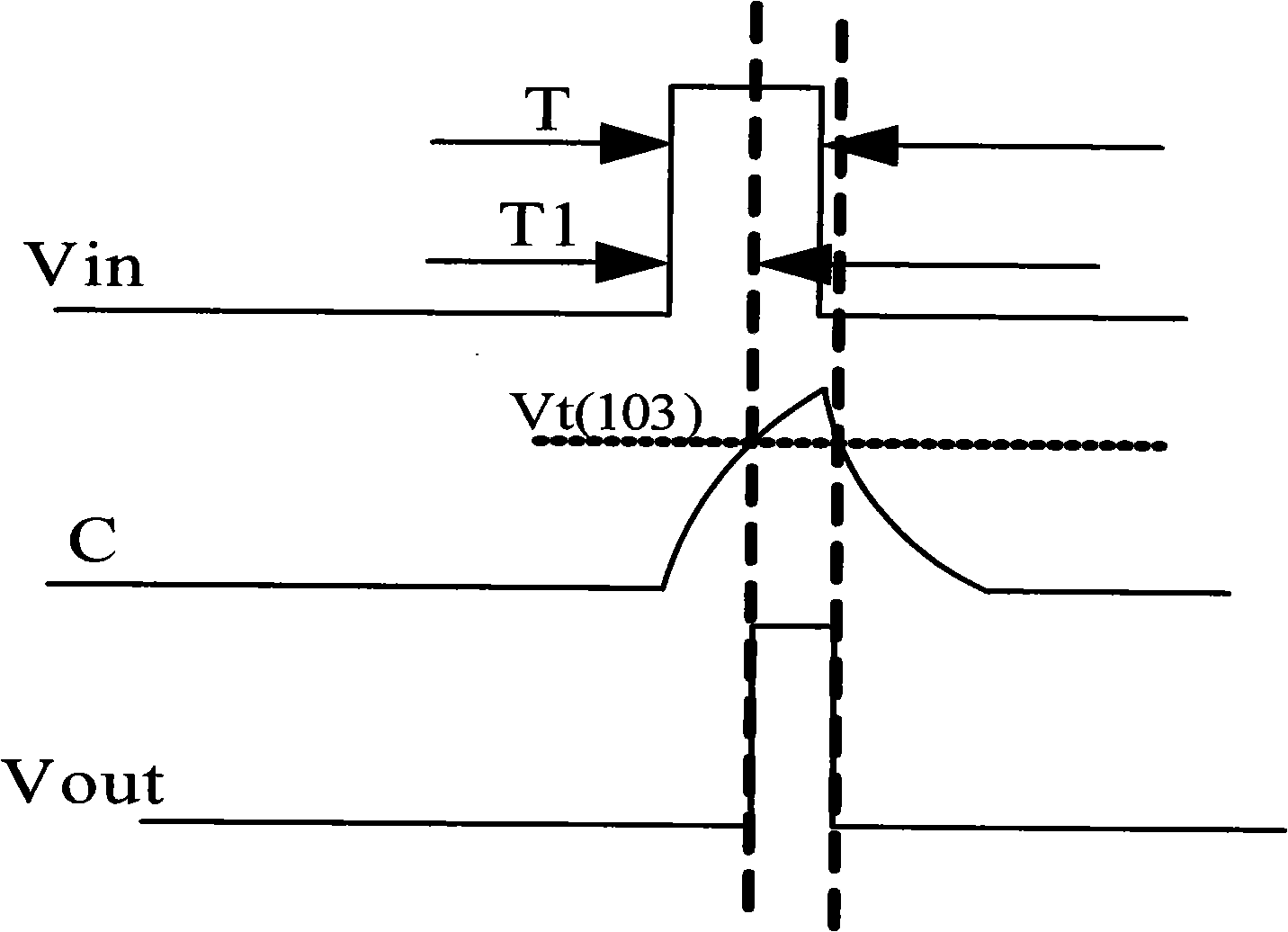
[0012] The above two structures have a common disadvantage, that is, in the case of continuous input of burrs with a pulse width of T3, T3 is less than the preset burr removal width T, and burr removal errors will still occur, such as Figure 5 , Image 6 shown

Method used


Image

  • A burr judgement and elimination circuit
  • A burr judgement and elimination circuit
  • A burr judgement and elimination circuit

Examples


Embodiment Construction

[0033] The following is based on Figure 7 to Figure 11 , a preferred embodiment of the present invention is given and described in detail, so that the functions and features of the present invention can be better understood.

[0034] Figure 7 It is a structural block diagram of the burr judgment and elimination circuit of the present invention. Such as Figure 7 As shown, the glitch judging and eliminating circuit of the present invention includes an RC delay circuit for detecting the glitch width. A delay output circuit connected to the output of the RC delay circuit is used to eliminate glitches generated under specific conditions. The front end A and the back end B of the RC delay circuit are connected to a feedback circuit, and the output of the feedback circuit returns to the back end C of the RC delay circuit. The RC delay circuit controls the feedback circuit to perform an accelerated reset after detecting a glitch, and accelerates the setting through the feedback...


PUM


Abstract

The present invention discloses a burr eliminating circuit which comprises a delay module which is used for detecting the width of the burr and a delay output module for eliminating the burr problem generated in specific condition. The delay module is connected with a feedback control circuit module. The delay module controls the feedback control circuit module to reset with an accelerated speed when the burr is detected and sets with an accelerated speed when the valid data is detected. The circuit of the invention totally satisfies the functions of determining and eliminating the burr and can expands the width of the valid narrow pulsewidth signal to a safe width for securing the safe operation.

Description

technical field [0001] The present invention relates to the design of analog integrated circuits in the field of microelectronics. Specifically, it is a circuit structure that uses RC delay to detect and eliminate burrs on input signals. The circuit structure can widen the effective signal with narrow pulse width to ensure its safety. Work. Background technique [0002] In chip work, the input of the signal needs to be accurate and clear. However, at present, the system application environment of many chips is poor, or due to strong external interference, at this time, the input signal of the chip will produce various types of glitches, which will seriously interfere with the integrity and correctness of the signal, and may cause the chip to malfunction. False triggering, working errors and other issues. In addition to the problems caused by regular glitches, there are also the following phenomena: [0003] Such as the clock input of ordinary circuits, if there is a glitc...

Claims


Application Information

Patent Timeline
IPC IPC(8): H03K5/125H03K5/1252H03K5/13H03K5/14
Inventor 王传芳程剑涛余维学王朝姚炜
Owner CHIPHOMER TECH SHANGHAI
Learn More