A smart antenna downlink wave bundle shaping method and its device

A beamforming method and smart antenna technology, applied in the field of mobile communication, can solve the problems of limited improvement in the real-time adaptive system performance of wireless channel changes, and difficulty in reflecting the performance of smart antennas.

Active Publication Date: 2008-09-17
深圳国人无线通信有限公司
View PDF1 Cites 17 Cited by
  • Summary
  • Abstract
  • Description
  • Claims
  • Application Information

AI Technical Summary

Problems solved by technology

However, the real-time adaptability of this method to wireless channel changes and the improvement of system performance are relatively limited, especial...

Method used


Image

  • A smart antenna downlink wave bundle shaping method and its device
  • A smart antenna downlink wave bundle shaping method and its device
  • A smart antenna downlink wave bundle shaping method and its device

Examples


Embodiment Construction

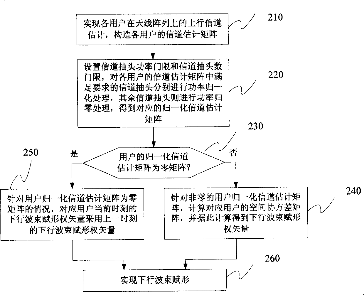
[0032]First, a brief description of the smart antenna downlink beamforming method of the present invention includes the steps of: ① realizing the uplink channel estimation of each user on the antenna array, and constructing the channel estimation matrix of each user; ② setting the channel tap power threshold and the channel tap number threshold, Perform power normalization processing on the channel taps that meet the requirements in the channel estimation matrix of each user, and perform power zero processing on the remaining channel taps to obtain the normalized channel estimation matrix of the corresponding user; ③ determine the normalized channel of the user Is the estimated matrix a zero matrix? If it is a zero matrix, go to step ⑤, otherwise, go to step ④; ④ normalize the channel estimation matrix for a non-zero user, calculate the spatial covariance matrix of the corresponding user, and calculate the downlink beamforming weight vector accordingly , go to step ⑥; ⑤ In the...


PUM


Abstract

The present invention relates to an intelligent antenna descending wave beam forming method and a device thereof, wherein the device comprises an antenna array (101), a multichannel amplifying unit (102), a multichannel transceiver unit (103), an ascending baseband processing unit (105) and the following components which are connected in sequence: a channel estimating and normalization processing unit (104), a space covariance matrix generating unit (106), a descending wave beam forming authority generating unit (107) and a descending wave beam forming unit (108). The method comprises the following procedures: setting a channel estimation window length W, and constructing each user ascending channel estimation matrix H(k); setting a channel tap power threshold PD and a channel tap number threshold ND, and combining the estimated channel tap power for real-time measuring P1(k) to obtain a power normalization ascending channel estimation matrix H(k) which satisfies the request of the channel tap; and calculating and generating a corresponding space covariance matrix R(k)=H(k)*(H(k))(H) and a descending wave beam forming authority vector w(k) according to that H(k) is not equal to 0/M*w and forming, or generating a descending wave beam forming authority vector w(k)(t)=w(k)(t-1) according to H(k)=0/M*w.

Description


Claims


Application Information

Patent Timeline
Owner 深圳国人无线通信有限公司
Why Eureka
Try Eureka