Copper alloy for an electric connecting device

A copper alloy, electrical connection technology, applied in the direction of metal/alloy conductors, circuits, conductive materials, etc., can solve problems such as poor strength

Inactive Publication Date: 2008-09-17
FURUKAWA ELECTRIC CO LTD
View PDF0 Cites 6 Cited by
  • Summary
  • Abstract
  • Description
  • Claims
  • Application Information

AI Technical Summary

Problems solved by technology

However, these alloys have poor strength and are therefore not suitable as spring materials

Method used


Image

  • Copper alloy for an electric connecting device
  • Copper alloy for an electric connecting device
  • Copper alloy for an electric connecting device

Examples


Embodiment

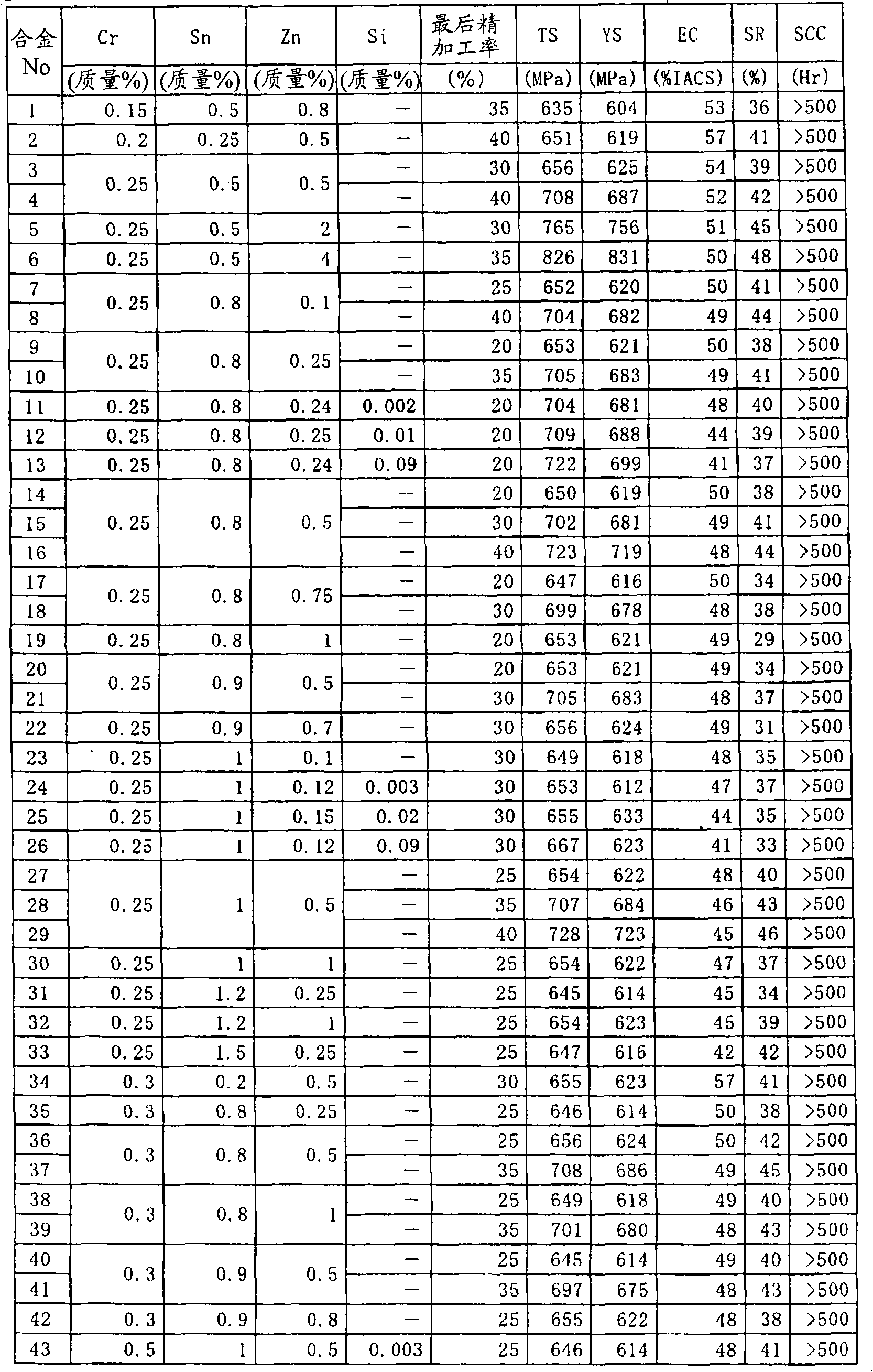
[0037] Various copper alloys are cast into book-shaped molds with a thickness of 30 mm x width 120 mm x length 180 mm in a high-frequency air melting furnace at a melting temperature of about 1200-1250 °C and a furnace temperature of about 1200 °C. The obtained ingot is kept at about 950-1000° C. for 1 hour in an air heating furnace, and then processed by hot rolling to a thickness of about 12-13 mm. And this hot-rolled sheet was surface-cut, and it processed into the sheet|seat of thickness about 10mm.

[0038] Cold working and heat treatment were repeated, and a flat plate (strip) with a thickness of 0.5 mm was produced from this plate. The Cr precipitation treatment is heat treatment at a temperature of 400-450° C. for 2-5 hours, and the final finishing rate is 10-40%.

[0039] In addition, commercially available copper alloys and non-ferrous materials were obtained with a plate thickness of 0.5 mm. The copper alloys are C2600, C2680, C5111, C5191 and C7701, and the stain...


PUM

PropertyMeasurementUnit
tensile strengthaaaaaaaaaa
yield strengthaaaaaaaaaa

Abstract

A copper alloy for electrical connecting device of 600 MPa or higher tensile strength (TS), 560 MPa or higher 0.2% yield strength (YS), 40%IACS or higher electrical conductivity (EC) and 500 hr or longer breaking time exhibited in a stress corrosion cracking test (SCC) under loading of 80% of 0.2% yield strength (YS), which copper alloy is composed of 0.1 to 1 mass% Cr, 0.1 to 5.0 mass% Zn, 0.1 to 2.0 mass% Sn and the balance unavoidable impurities and Cu.

Description

technical field [0001] The present invention relates to copper alloys for wiring connection equipment. Background technique [0002] Electrical connection devices are widely used in electrical connection parts such as sockets and light switches of electrical equipment, and the connection parts generally use metal, and the electrical connection is performed through contact between the metals. There are two types of electrical connection parts, one is the connection with the power supply wire (copper wire), and the other is the connection with the power supply object. Conventionally, pure copper with excellent electrical conductivity or a copper alloy (such as C14410) with improved heat resistance by adding a small amount (≤0.2%) of Sn or Ag has been used for the contact portion. [0003] These materials have very low strength. Therefore, in order to maintain the connection with the above-mentioned power supply object, the connection part is made of a high-strength material ...

Claims


Application Information

Patent Timeline
Patent Type & Authority Applications(China)
IPC IPC(8): C22C9/04C22C9/02C22C9/10H01B1/02H01R13/03
CPCH01B1/026C22C9/00C22C9/02C22C9/04C22F1/08H01R13/03
Inventor 三原邦照江口立彦
Owner FURUKAWA ELECTRIC CO LTD
Why Eureka
Try Eureka