Optical power therapentic equipment
A photodynamic therapy and light source technology, applied in the field of medical devices, can solve the problems of weakened guidance, inability to objectively evaluate the treatment effect, and inability to automatically monitor the photodynamic therapy process, and achieve the effect of enhancing scientificity and improving the level of informatization.
- Summary
- Abstract
- Description
- Claims
- Application Information
AI Technical Summary
Problems solved by technology
Method used
Image

Examples
Embodiment Construction
[0020] The present invention will be further described below in conjunction with the accompanying drawings and embodiments.
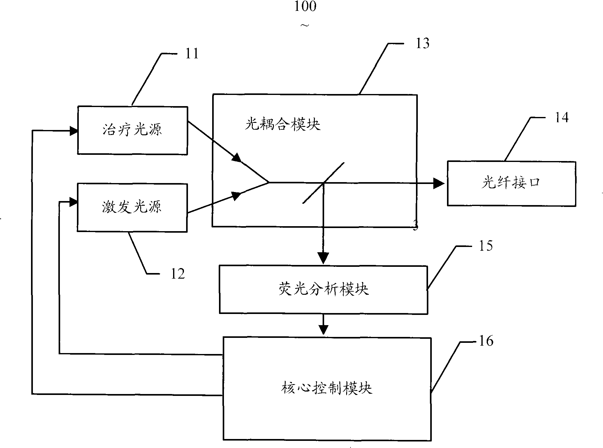
[0021] Please refer to figure 1 , is a schematic structural diagram of the basic principle of the photodynamic therapy device of the present invention. The photodynamic therapy device 100 includes a treatment light source 11 and a fluorescence excitation light source 12, an optical coupling module 13, an optical fiber interface 14, a fluorescence analysis module 15 and a core control module 16, and the treatment light source 11 and the fluorescence excitation light source 12 are connected to the optical coupling module 13, the optical coupling module 13 couples the obtained two-way light to the same optical fiber interface 14 for output, and then a dedicated optical fiber is connected to the optical fiber interface 14 to transmit the coupled light to the target site. The optical coupling module 13 transmits the fluorescence returned by the optical fibe...
PUM
 Abstract
Description
Claims
Application Information