
Capacitance type micro-accelerometer

An accelerometer and capacitor technology, applied in the field of MEMS micro-inertial instruments, can solve the problems of discounted advantages of micro-sensors, complex circuits, low resolution, etc., to simplify system complexity, eliminate common mode noise, and reduce processing costs and difficulties. Effect

Inactive Publication Date: 2011-05-11
TSINGHUA UNIV
View PDF0 Cites 2 Cited by
  • Summary
  • Abstract
  • Description
  • Claims
  • Application Information

AI Technical Summary

Problems solved by technology

Traditional signal readout and processing circuits are made of discrete components, which not only have large volume and low resolution, but also have problems in repeatability and reliability, which form a great contrast with micromechanical sensors, making microsensors have great advantages Most of the existing micro-accelerometers use sensors and signal processing circuits to form a system on a printed circuit board (PCB for short), which is not only large in size, complex in circuit, but also hand-made, so there are problems of high cost and low yield. question

Method used


Image

  • Capacitance type micro-accelerometer
  • Capacitance type micro-accelerometer
  • Capacitance type micro-accelerometer

Examples


Embodiment Construction

[0016] The principle, structure and specific implementation of the present invention will be further described below in conjunction with the accompanying drawings.

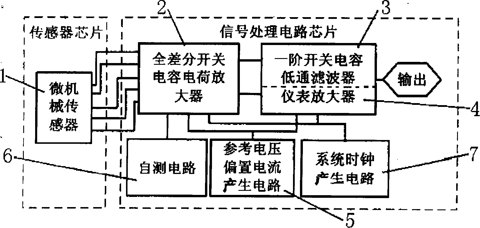
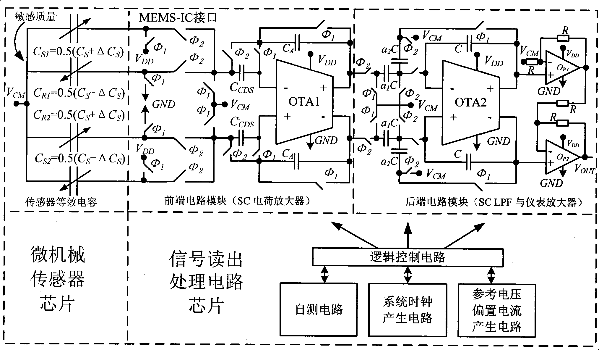
[0017] Such as figure 1 , figure 2 The system block diagram and implementation details of the capacitive micro-accelerometer shown mainly include two chips, a micro-mechanical sensor and a signal processing circuit, using a two-chip solution, integrated separately, and packaged in the system.

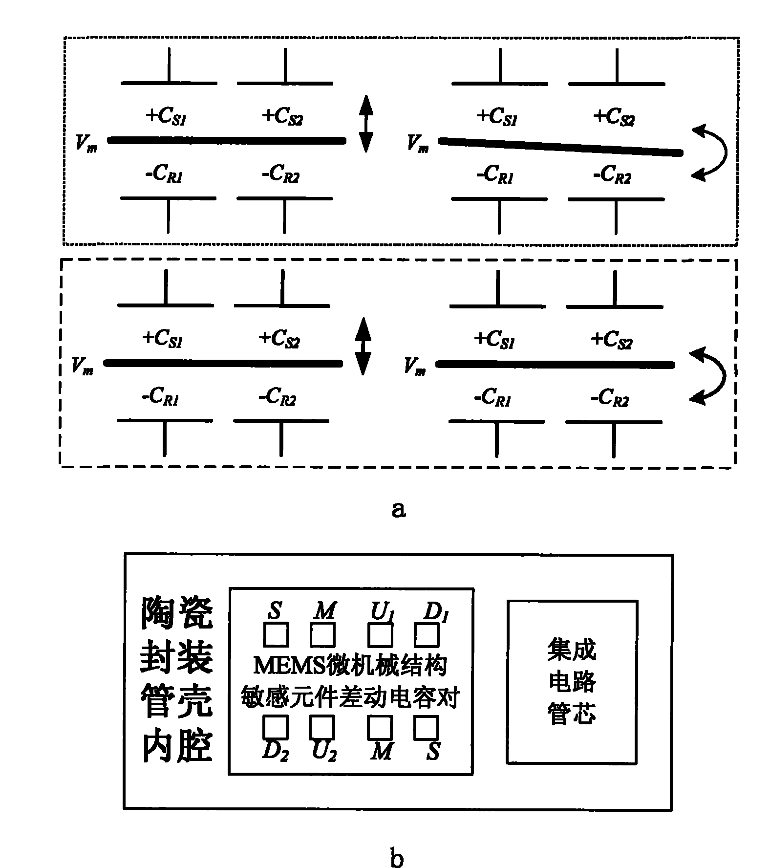
[0018] The micromechanical sensor in the present invention adopts a fully differential micromechanical structure, realizes two pairs of differential capacitors, a high cross-coupling suppression design of sensitive elements and electrical interfaces, and achieves compatibility between the micromechanical sensor and the signal processing circuit.

[0019] Signal readout among the present invention, processing circuit, comprise the fully differential SC charge amplifier 2 that gain can be adjusted, as the front end circuit ...


PUM


Abstract

The invention relates to a capacitive micro-accelerometer which adopts the design of a bulk-silicon processed micro-mechanical structure and the design of an integrated circuit, which pertains to the field of MEMS micro-inertial instruments. The capacitive micro-accelerometer adopts two chips of a micro-mechanical sensor and a signal processing circuit for respective integration, the capacitive micro-accelerometer is carried out by the overall packaging and finally realizes an internal structure of the packaged system; the micro-mechanical sensor of the invention adopts a full-differential micro-mechanical structure sensitive element to be matched with a follow-up circuit; the signal processing circuit comprises a full-differential switched capacitor charge amplifier front-end circuit module with adjustable gain, a back-end cascade circuit module which is composed of a first-order switched capacitor low-pass filter and an instrument amplifier and an auxiliary circuit module which is composed of a reference voltage and bias current generating circuit, a self-test circuit and a clock generating circuit. The two-chip proposal of the system of the invention carries out the respective integration and overall packaging, thus simplifying the complexity of the system, reducing the processing cost and the difficulty and improving the performance and the yield.

Description

technical field [0001] The invention belongs to the field of MEMS micro-inertial instruments. In particular, it relates to a capacitive micro-accelerometer which adopts bulk silicon processing micro-mechanical structure design and integrated circuit design. Background technique [0002] Capacitive micro-accelerometers are widely used in civilian industrial control and military fields. Capacitive micro-accelerometers have the advantages of low power consumption, high sensitivity, simple structure, and inherent low temperature sensitivity. The interface between the mechanical sensor and the signal readout and processing circuit is the main problem in the design of the capacitive micro-accelerometer. In many cases, the interface circuit determines the resolution of the micro-accelerometer to a certain extent. Traditional signal readout and processing circuits are made of discrete components, which not only have large volume and low resolution, but also have problems in repeata...

Claims


Application Information

Patent Timeline
Patent Type & Authority Patents(China)
IPC IPC(8): G01P15/125
Inventor 刘民杰刘云峰万蔡辛董景新
Owner TSINGHUA UNIV
Learn More