
A self-excited and compensated bandgap reference voltage source

A reference voltage source and compensation circuit technology, applied in the direction of adjusting electrical variables, instruments, control/regulation systems, etc., can solve problems such as temperature characteristic output voltage stability limitations, achieve the effect of weakening offset voltage and improving power supply voltage rejection ratio

Active Publication Date: 2020-12-04
XIAN UNIV OF POSTS & TELECOMM
View PDF3 Cites 0 Cited by
  • Summary
  • Abstract
  • Description
  • Claims
  • Application Information

AI Technical Summary

Problems solved by technology

However, there are operational amplifiers in the traditional bandgap reference voltage source circuit, and the temperature characteristics and output voltage stability of the bandgap reference voltage source are largely affected by factors such as the offset voltage (offset) of the operational amplifier and power supply voltage rejection ratio (PSRR). get restricted

Method used


Image

  • A self-excited and compensated bandgap reference voltage source
  • A self-excited and compensated bandgap reference voltage source
  • A self-excited and compensated bandgap reference voltage source

Examples


Embodiment Construction

[0029] The present invention will be described in detail below in conjunction with the accompanying drawings.

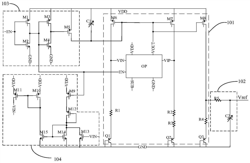
[0030] like figure 1 As shown, the self-excited compensation bandgap reference voltage source provided by the present invention is based on the traditional bandgap reference voltage source 101, adding a self-excited compensation circuit 104, a switch circuit 103, a capacitor C1 and a low-pass filter device 102.

[0031] The traditional bandgap reference voltage source 101 includes PMOS transistors M6, M7, M8, an operational amplifier OP, resistors R1, R2, R3, R4, and transistors Q1, Q2, and Q3; VIN and VIP are two input ports of the operational amplifier OP, The output VOUT of the operational amplifier OP can provide voltage for the gates of the PMOS transistors M6, M7 and M8, thereby making the PMOS transistors M6, M7 and M8 all work in the saturation region; the transistors Q1 and Q2 are two identical transistors (I SS1 =I SS2 ), the width-to-length ratios and w...


PUM


Abstract

The invention provides a self-excited compensation type band-gap reference voltage source, thereby solving a technical problem that the temperature characteristics and output voltage stability of theband-gap reference voltage are largely affected by the operational amplifier offset voltage, power supply voltage rejection ratio (PSRR), and other factors because of the operational amplifier in theconventional band-gap reference circuit. The self-excited compensation type band-gap reference voltage source comprises a conventional band-gap reference voltage source including an operational amplifier OP, a power input port VDD, and a voltage output port Vref. Besides, the self-excited compensation type band-gap reference voltage source is characterized by also including a switching circuit anda self-excitation compensation circuit. The self-excitation compensation circuit is used for providing feedback for one input VIN of the operational amplifier OP, so that the input VIN and another input VIP of the operational amplifier are kept to be at the same voltage values; and the switching circuit is used for controlling the operation and on / off of the self-excitation compensation circuit.

Description

technical field [0001] The invention relates to the technical field of integrated circuits, in particular to a bandgap reference voltage source capable of self-excitation compensation. Background technique [0002] The reference source includes a reference current source and a reference voltage source, which respectively provide a reference current and a reference voltage for the circuit. , Linear regulators, memory and power management chips are essential components. [0003] With the rapid development of the system on chip (SOC), it is required to use CMOS technology to design the analog integrated circuit unit. Traditional reference voltage sources such as Zener Reference and Buried Zener Reference are not suitable for the design of today's CMOS integrated circuits due to their high voltage, high power consumption and incompatibility with CMOS manufacturing processes . The bandgap reference source is widely used in CMOS circuits due to its comprehensive consideration o...

Claims


Application Information

Patent Timeline
Patent Type & Authority Patents(China)
IPC IPC(8): G05F1/565
CPCG05F1/565
Inventor 黄海生惠强李鑫
Owner XIAN UNIV OF POSTS & TELECOMM
Learn More