
Miniature folded dipole antenna with mirror-image structure for radio frequency recognition system

A radio frequency identification system and folded dipole technology, which are applied in the direction of radiating element structure, resonant antenna, antenna support/installation device, etc., can solve the problem that the size of the microstrip antenna is too large, the related technology has not been reported, and the effect is not ideal and other problems, to achieve the effect of small size, good radiation characteristics and simple structure

Inactive Publication Date: 2012-04-25
XIAMEN UNIV
View PDF3 Cites 0 Cited by
  • Summary
  • Abstract
  • Description
  • Claims
  • Application Information

AI Technical Summary

Problems solved by technology

[0004] For the current RFID antenna with a working frequency of less than 3GHz, the size of the conventional microstrip antenna is obviously too large. Even if it is miniaturized by inserting short-circuit pins and other technologies, the effect is still unsatisfactory
[0005] At present, there is no report on the related technology of combining the folded dipole antenna with the "mirror compensation" structure and applying it in the ISM frequency band (2.4-2.4835GHz) of the RFID system

Method used


Image

  • Miniature folded dipole antenna with mirror-image structure for radio frequency recognition system
  • Miniature folded dipole antenna with mirror-image structure for radio frequency recognition system
  • Miniature folded dipole antenna with mirror-image structure for radio frequency recognition system

Examples


Embodiment Construction

[0015] The present invention will be further described below in conjunction with embodiments and accompanying drawings.

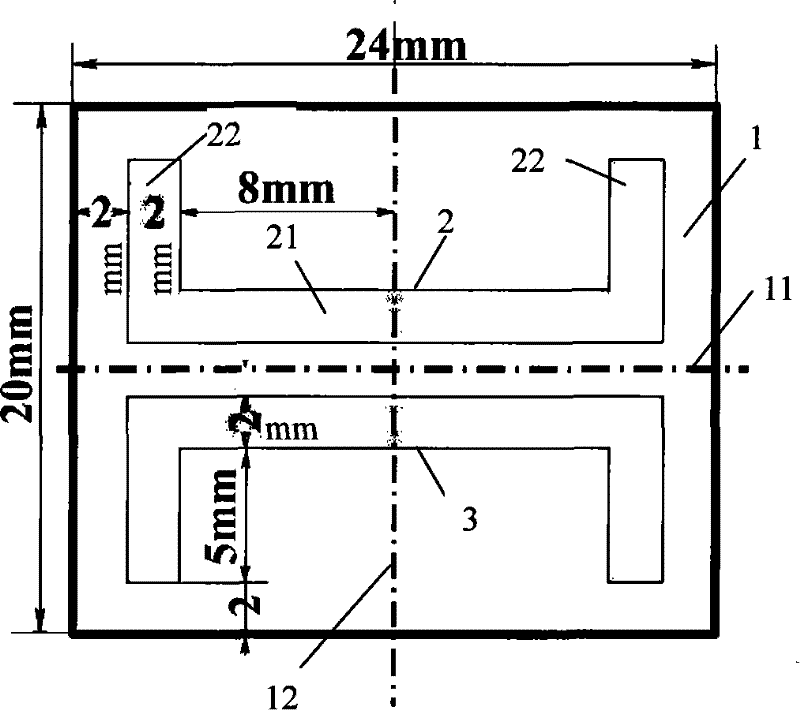
[0016] see figure 1 , the present invention is provided with a rectangular dielectric substrate 1 with a copper clad layer on one side, and the copper clad layer is etched into a metal dipole radiation patch 2 and a mirror image compensation patch 3 . The metal dipole radiating patch 2 and the mirror image compensation patch 3 have the same structural size, and are symmetrically arranged up and down with the transverse centerline 11 of the dielectric substrate 1 as the boundary. The metal dipole radiation patch 2 is provided with a straight arm 21 and two folded arms 22 , and the two folded arms 22 are symmetrically located at both ends of the long arm 21 and perpendicular to the long arm 21 . The metal dipole radiation patch 2 is provided with a middle disconnection gap (not shown in the figure, the middle disconnection gap may be a very small gap formed ...


PUM


Abstract

A miniaturized folded-dipole antenna with an enatiomorph used for a radio frequency identification device (RFID) system relates to a folded-dipole antenna and provides a miniaturized folded-dipole antenna with an enatiomorph used for the RFID system that is of small size, large bandwidth, and lower return loss and provided with omni-directional radiation characteristic. A medium substrate with one side covered with copper is arranged; the copper covered area of the medium substrate is provided with a metallic dipole radiation patch and a mirror image compensation patch; the metallic dipole radiation patch is provided with a straight-arm and two fold-arms, the two fold-arms are of the same size and being symmetrically located at the two ends of the straight-arm; an opened clearance is arranged on the horizontal center line of the straight-arm and is located on the center line of the straight-arm; the mirror image compensation patch and the metallic dipole radiation patch are of the same structure and size and are arranged symmetrically.

Description

technical field [0001] The invention relates to a dipole antenna, in particular to a miniaturized folded dipole antenna with a mirror image structure for a radio frequency identification system. Background technique [0002] Radio frequency identification (RFID) technology is a non-contact automatic identification technology realized by radio frequency communication that emerged in the 1990s. RFID tags have the characteristics of small size, large capacity, long life, and reusability. They can support fast reading and writing, non-visual identification, mobile identification, multi-target identification, positioning and long-term tracking management. Combined with other technologies, it can be used in logistics, manufacturing, public information services and other industries to achieve efficient management and operation and reduce costs. With the continuous improvement and maturity of security soft information-related technologies, the RFID series industry will become an em...

Claims


Application Information

Patent Timeline
Patent Type & Authority Patents(China)
IPC IPC(8): H01Q1/38H01Q9/16H01Q1/22
Inventor 游佰强林斌汤伟周建华刘舜奎李伟文
Owner XIAMEN UNIV
Learn More