Multilayer piezoelectric element and ejector using this

A piezoelectric element, lamination type technology, which is applied in the manufacture/assembly of piezoelectric/electrostrictive devices, fuel injection devices, electrical components, etc., and can solve problems such as insufficient improvement, change in displacement, and occurrence of cracks. and other problems, to achieve the effect of suppressing the change of displacement, suppressing stress concentration, and suppressing the occurrence of cracks

Active Publication Date: 2008-09-24
KYOCERA CORP
View PDF5 Cites 2 Cited by
  • Summary
  • Abstract
  • Description
  • Claims
  • Application Information

AI Technical Summary

Problems solved by technology

For this reason, the stress accompanying the displacement concentrates around the central part of the stacking direction of the multi-layer piezoelectric element, causing problems such as cracks.
[0018] As the improvement method, although there are methods shown in Patent Documents 4 and 5, they are mostly used under harsh conditions such as high electric field and high pressure for long-term continuous operation. Under such conditions, it is still impossible to say that Sufficient improvement may cause stress to concentrate on the outer periphery of the center of the element, resulting in cracks, peeling, or changes in displacement
[0019] In particular, there is a high risk of occurrence of the above-mentioned problems in a simultaneous firing type multi-layer piezoelectric element or a type in which at least a part of the outer periphery of the piezoelectric body is constrained.
[0020] In addition, there may be a resonance phenomenon in which the displacement behavior of each piezoelectric layer is consistent, which may generate a sound, and generate a high-order harmonic signal that is an integer multiple of the driving frequency and become a noise component.

Method used


Image

  • Multilayer piezoelectric element and ejector using this
  • Multilayer piezoelectric element and ejector using this
  • Multilayer piezoelectric element and ejector using this

Examples


no. 1 approach

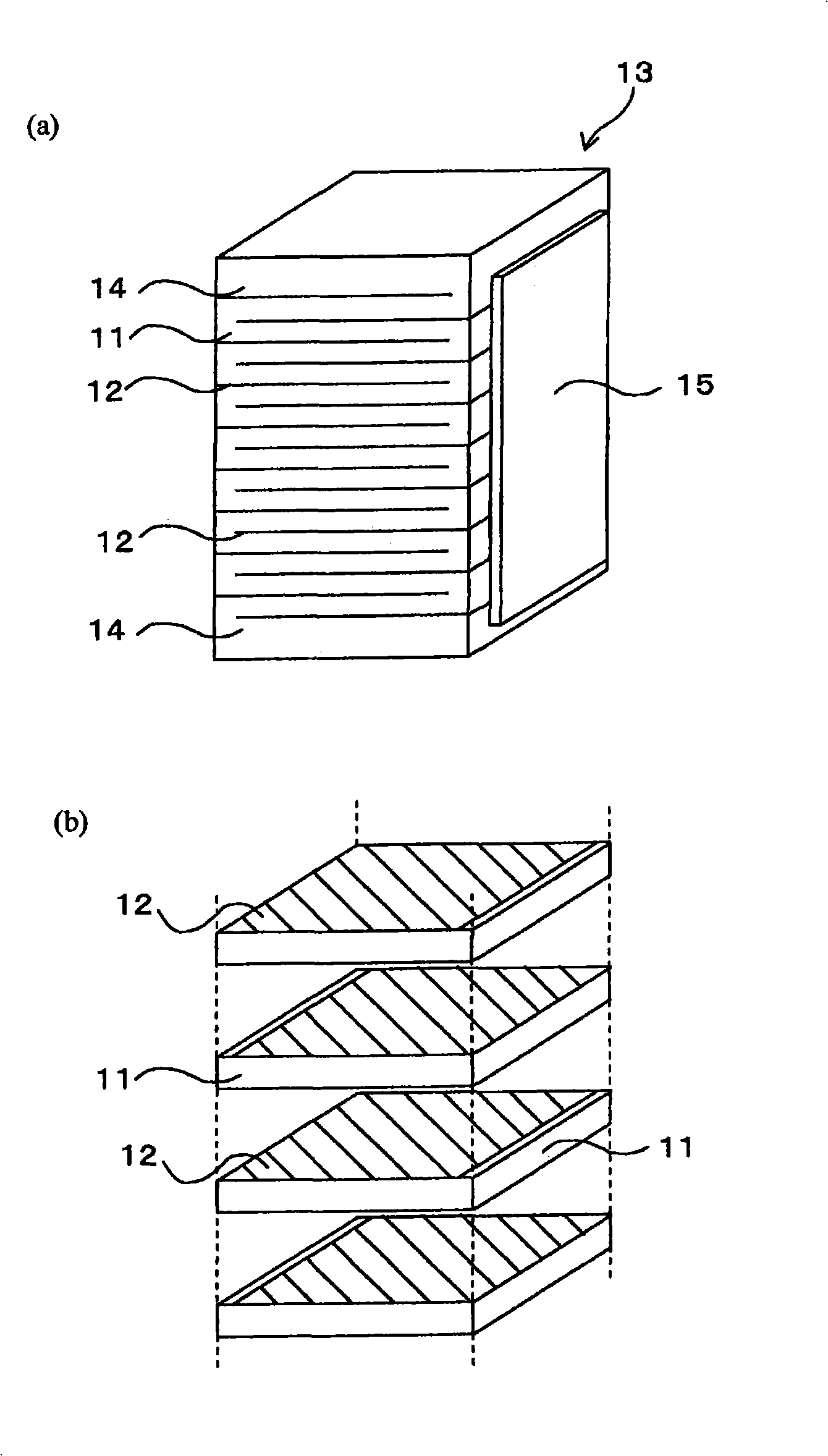
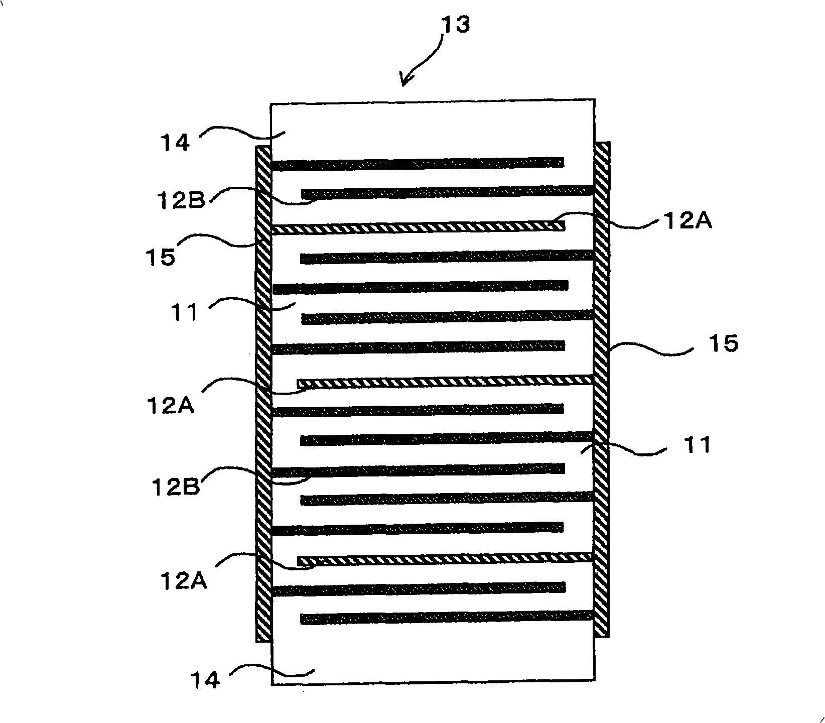
[0042] The multi-layer piezoelectric element according to an embodiment of the present invention will be described in detail with reference to the drawings. figure 1 (a) is a perspective view showing the multi-layer piezoelectric element according to this embodiment, figure 1 (b) is a partial perspective view showing the laminated state of the piezoelectric body layer and the metal layer in the multi-layer piezoelectric element. figure 2 It is a cross-sectional view of the laminated structure of the metal layer in contact with the laminated body layer of the multi-layer piezoelectric element according to the first embodiment.

[0043] Such as figure 1 As shown, this multi-layer piezoelectric element has a laminate 13 in which piezoelectric layers 11 and metal layers 12 are alternately laminated, and a pair of external electrodes 15 are respectively joined to each other. The external electrodes 15 are opposed to each other in the laminate layer 13. The end of the metal layer 12...

no. 2 approach

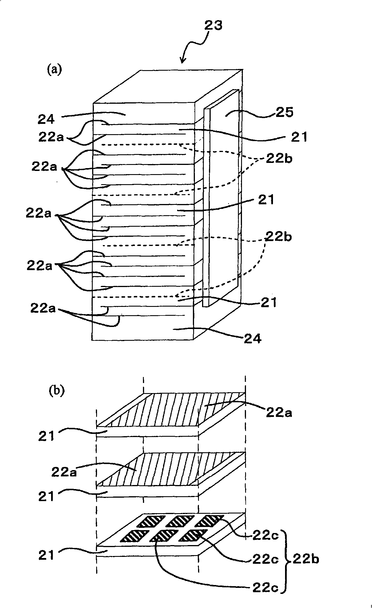
[0090] The multi-layer piezoelectric element according to the second embodiment of the present invention will be described in detail. FIG. 13(a) is a perspective view showing the multi-layer piezoelectric element according to this embodiment, and FIG. 13(b) is a partial perspective view of the laminated state of the piezoelectric layer and the metal layer in FIG. 13(a).

[0091] Such as image 3 As shown in (a) and (b), the multi-layer piezoelectric element of this embodiment has a plurality of piezoelectric body layers 21 and a plurality of metal layers 22a, 22b (hereinafter collectively referred to as "metal layers 22") stacked alternately. The laminated body 23 is provided with a pair of external electrodes 25 (one external electrode is not shown) on opposing side surfaces of the laminated body 23. Each metal layer 22 is not formed on the entire main surface of the piezoelectric body layer 21, that is, constitutes a so-called partial electrode structure. The plurality of metal ...

Embodiment 1

[0123] (Example 1) A piezoelectric actuator composed of the multi-layer piezoelectric element of the present invention was produced as follows.

[0124] First, lead zirconate titanate (PbZrO) with an average particle diameter of 0.4μm is mixed. 3 -PbTiO 3 The calcined powder, binder, and plasticizer of piezoelectric ceramics with) as the main components are made into a slurry, and a ceramic printed circuit board that becomes the piezoelectric body 11 with a thickness of 150 μm is produced by a doctor blade method or the like.

[0125] On one surface of the ceramic printed circuit board, a conductive paste containing a binder added to a silver-palladium alloy (95% by mass silver to 5% by mass palladium) was printed by a screen printing method. At this time, in the part where the other metal layer 12B is formed, a conductive paste with a binder added to a silver-palladium alloy (95% by mass of silver-5% by mass of palladium) is used for printing so that it becomes 5 or 10 μm after f...


PUM

PropertyMeasurementUnit
softening pointaaaaaaaaaa
particle sizeaaaaaaaaaa
thicknessaaaaaaaaaa

Abstract

In a laminated piezoelectric element, a plurality of piezoelectric layers and a plurality of metal layers are alternately laminated. The metal layers include a plurality of high resistance metal layers having an electrical resistance higher than electrical resistances of the adjacent metal layers on the both sides. The high resistance metal layers are regularly arranged by sandwiching a plurality of metal layers other than the high resistance metal layers. In another laminated piezoelectric element, a plurality of piezoelectric layers and a plurality of metal layers are alternately laminated, and at least one layer of the metal layers is composed of a plurality of partial metal layers arranged between the piezoelectric layers.

Description

Technical field [0001] The present invention relates to a multi-layer piezoelectric element (hereinafter sometimes simply referred to as an "element") and an ejection device, and particularly to a multi-layer piezoelectric element and an ejection device suitable for continuous driving under high voltage / high pressure for a long time. Background technique [0002] Conventionally, as a device using a laminated piezoelectric element, there has been a piezoelectric actuator in which piezoelectric body layers and metal layers are alternately laminated. Piezoelectric actuators are generally divided into two types, one is a simultaneous firing type, and the other is a stack type in which a piezoelectric ceramic formed by a piezoelectric body and a metal layer of a plate-shaped body are alternately laminated. Among them, from the viewpoint of achieving low voltage and reducing manufacturing costs, most of the simultaneous firing type piezoelectric actuators are used. Regarding the simult...

Claims


Application Information

Patent Timeline
Patent Type & Authority Applications(China)
IPC IPC(8): H01L41/083H01L41/187H01L41/22F02M51/06H01L41/277
Inventor 寺园正喜鹤丸尚文中村成信山元坚
Owner KYOCERA CORP
Why Eureka
Try Eureka