Buffering type air hoister

A hoist and pneumatic technology, applied in the field of buffer type pneumatic hoist, can solve the problems of wear, damage and severe impact of the feeding pipe, and achieve the effects of reducing wind resistance loss, prolonging service life and reducing wind pressure resistance.

Inactive Publication Date: 2008-10-01
黄华静
View PDF1 Cites 2 Cited by
  • Summary
  • Abstract
  • Description
  • Claims
  • Application Information

AI Technical Summary

Problems solved by technology

[0002] The material receiving device on the air lifter with the patent No. 90221521.3 in the prior art is mainly composed of a feed pipe and an outer casing; the connection and structure between them are: the lower end of the outer casing is connected to the feeding chassis and installed In the discharge pit for granular materials, the upper end of the feeding pipe is connected to the unloader on the elevator, and the lower end of the feeding pipe is inserted into the outer casing. There is a gap between the outer wall of the feeding pipe and the inner wall of the outer casing, causing the feeding pipe It cannot be stably fixed on the ground, so the weight of the air hoist composed of the unloader connected to it, the motor on the unloader, the fan and the dust collector can only be hoisted on the girder of the house with iron wires

Method used


Image

  • Buffering type air hoister
  • Buffering type air hoister
  • Buffering type air hoister

Examples


Example Embodiment

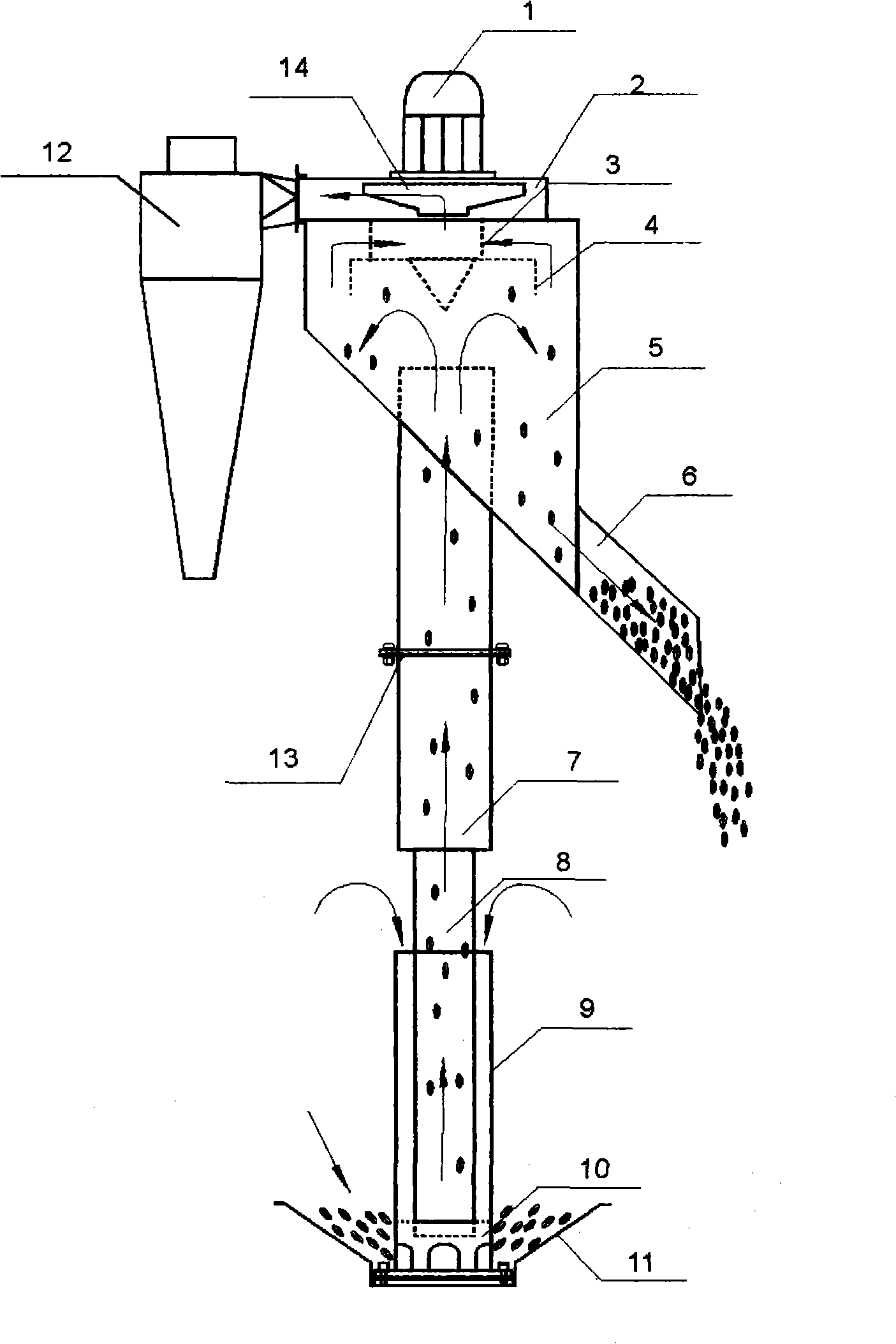
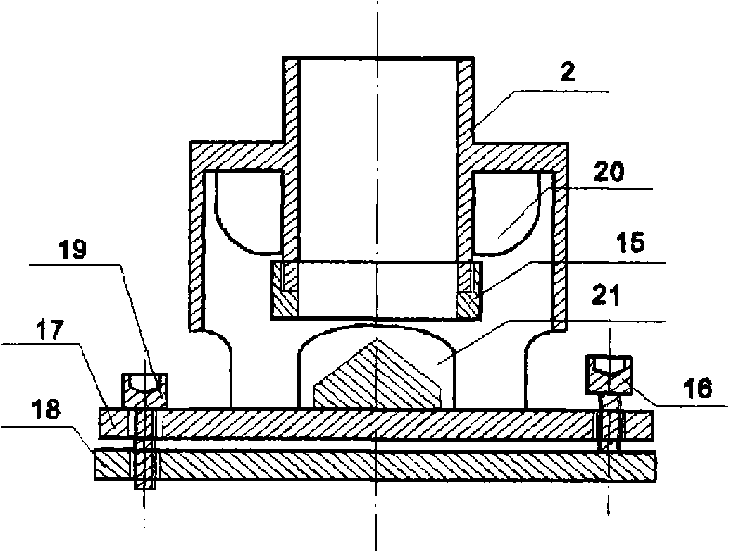
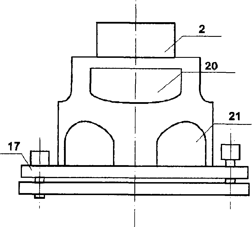
[0014] Such as figure 1 , figure 2 , image 3 , Figure 4 , Figure 5 with Figure 6 Shown: a buffer type pneumatic hoist of the present invention is mainly composed of a motor 1, a fan 2, a discharger 5, a dust collector 12 on the side where the discharger 5 is installed, a pressure discharge pipe 6 and a feeder The composition of the catcher composed of the pipe and the outer sleeve is characterized in that: the fan 2 connected with the motor 1 is directly installed on the top of the discharger 5, and the working surface of the fan impeller 14 communicates with the working chamber of the discharger; pressure discharge The tube 6 is connected below the unloader 5 and communicates with the working chamber of the unloader 5; the feed tube is composed of the buffer tube 7 in the upper section and the acceleration tube 8 in the lower section. The upper end of the buffer tube 7 is connected to the discharge of the elevator The device 5 is connected, and below the acceleration tube 8,...


PUM


Abstract

The invention relates to a buffer-typed pneumatic lifter. The buffer-typed pneumatic lifter essentially consists of a motor 1, an air blower 2, a discharger 5, a dust collector 12, a pressure discharging tube 6 and a material acceptor and is characterized in that the air blower 2 which is connected with the motor 1 is directly installed at the center of the top part of the discharger 5; a feeding tube consists of a buffer tube 7 of an upper section and an accelerating tube 8 of a lower section, a feeding base 10 is arranged under the accelerating tube 8 and is provided with a plurality of air inlets 20 and a plurality of feeding ports 21; an adjusting disc 17 of the end port of the feeding base 10 is fixed on a ground fixed disc 18 inside a material accepting disc 11, and the lower end of an outer sleeve 9 is also provided with feeding ports 22 which are matched with the feeding ports 21 mutually. The buffer-typed pneumatic lifter has the advantages that (1) the pressure of the materials can be quickly reduced after being buffered by the buffer tube 7 after the accelerating lift of the accelerating tube 8, therefore, the impact between the materials and the top part of the discharger is reduced and the crushing rate of the material is effectively reduced; (2) wind speed is lowered after the material is buffered by the buffer tube 7, the resistance of wind pressure is decreased and wind resistance loss is reduced; (3) since the weight of the whole machine is fixed on the ground fixed disc, the gravity center of the whole machine is stable, the lifter is not needed to be hung on the beam of a house by an iron wire, and the usage is safe and reliable.

Description

technical field [0001] The invention relates to a buffer type air hoist used for lifting granular materials (paddy, wheat, brown rice, corn and feed, etc.). Background technique [0002] The material receiving device on the air lifter with the patent No. 90221521.3 in the prior art is mainly composed of a feed pipe and an outer casing; the connection and structure between them are: the lower end of the outer casing is connected to the feeding chassis and installed In the discharge pit for granular materials, the upper end of the feeding pipe is connected to the unloader on the elevator, and the lower end of the feeding pipe is inserted into the outer casing. There is a gap between the outer wall of the feeding pipe and the inner wall of the outer casing, causing the feeding pipe It cannot be stably fixed on the ground, so the weight of the air hoist composed of the unloader connected to it, the motor on the unloader, the fan and the dust collector can only be hoisted on the ...

Claims


Application Information

Patent Timeline
IPC IPC(8): B65G53/04B65G53/34B65G53/40B65G53/58
Inventor 黄华静
Owner 黄华静
Why Eureka
Try Eureka