Electroformed mold and manufacturing method therefor

A manufacturing method and electroforming technology, applied in electroforming and electrolysis processes, etc., can solve the problems of deformation of medium flow channels, difficulty in forming forming surfaces with complex shapes, and inability to ensure rigidity, etc., and achieve good durability, excellent cooling performance, The effect of a reliable connection

Inactive Publication Date: 2008-10-01
TOYODA GOSEI CO LTD
View PDF3 Cites 6 Cited by
  • Summary
  • Abstract
  • Description
  • Claims
  • Application Information

AI Technical Summary

Problems solved by technology

Therefore, there is a problem that it is difficult to deposit the electroformed layer on the portion indicated by the shaded portion.
Thus, the part of the shell deposited on the peripheral recess of the solid body cannot be guaranteed to have sufficient rigidity
As a result, there is concern that the injection pressure of the molding hole will deform the medium flow channel
In addition, since the molding surface is formed of a thin plate, it is difficult to form a molding surface with a complicated shape

Method used


Image

  • Electroformed mold and manufacturing method therefor
  • Electroformed mold and manufacturing method therefor
  • Electroformed mold and manufacturing method therefor

Examples


no. 1 approach

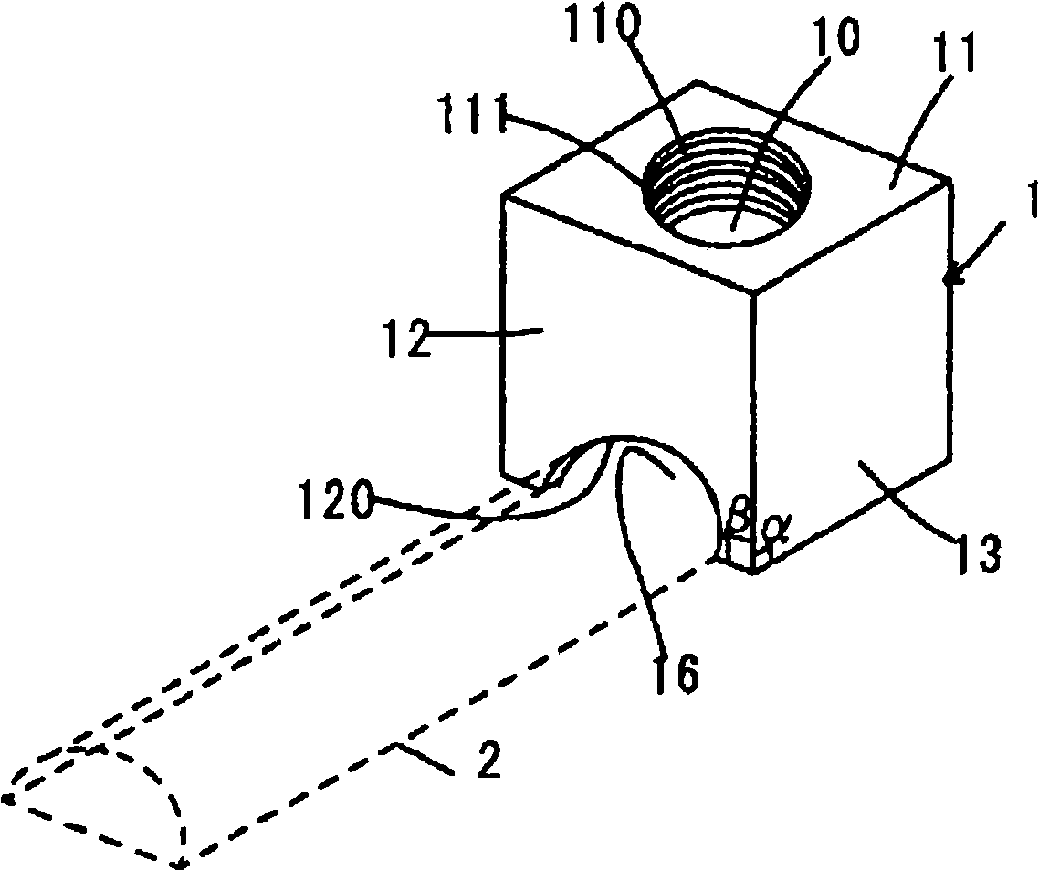
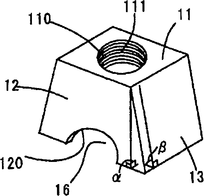
[0080] According to the electroforming mold of the present invention, there are medium flow passages formed in the electroforming shell. Preferably, the cross-sectional shape of the medium flow channel is a non-recessed shape, such as semicircle, rectangle, square and trapezoid. The non-lower concave shape refers to a shape in which, when projecting the medium flow channel from above, there is no lower portion hidden by its upper portion from being seen from above. If the shape of the medium flow channel is a lower concave shape, when the medium flow channel is projected from above, a part of it is covered by its upper part and cannot be seen from above. Compared with the above case, the shape of the medium flow channel is not lower. In the case of shapes, the deposition of electroformed metal can be improved.

[0081] Preferably, the medium flow channel has a width ranging from 5 mm to 15 mm. In the case where the width of the medium flow channel is less than 5 mm, the flow...

no. 2 approach

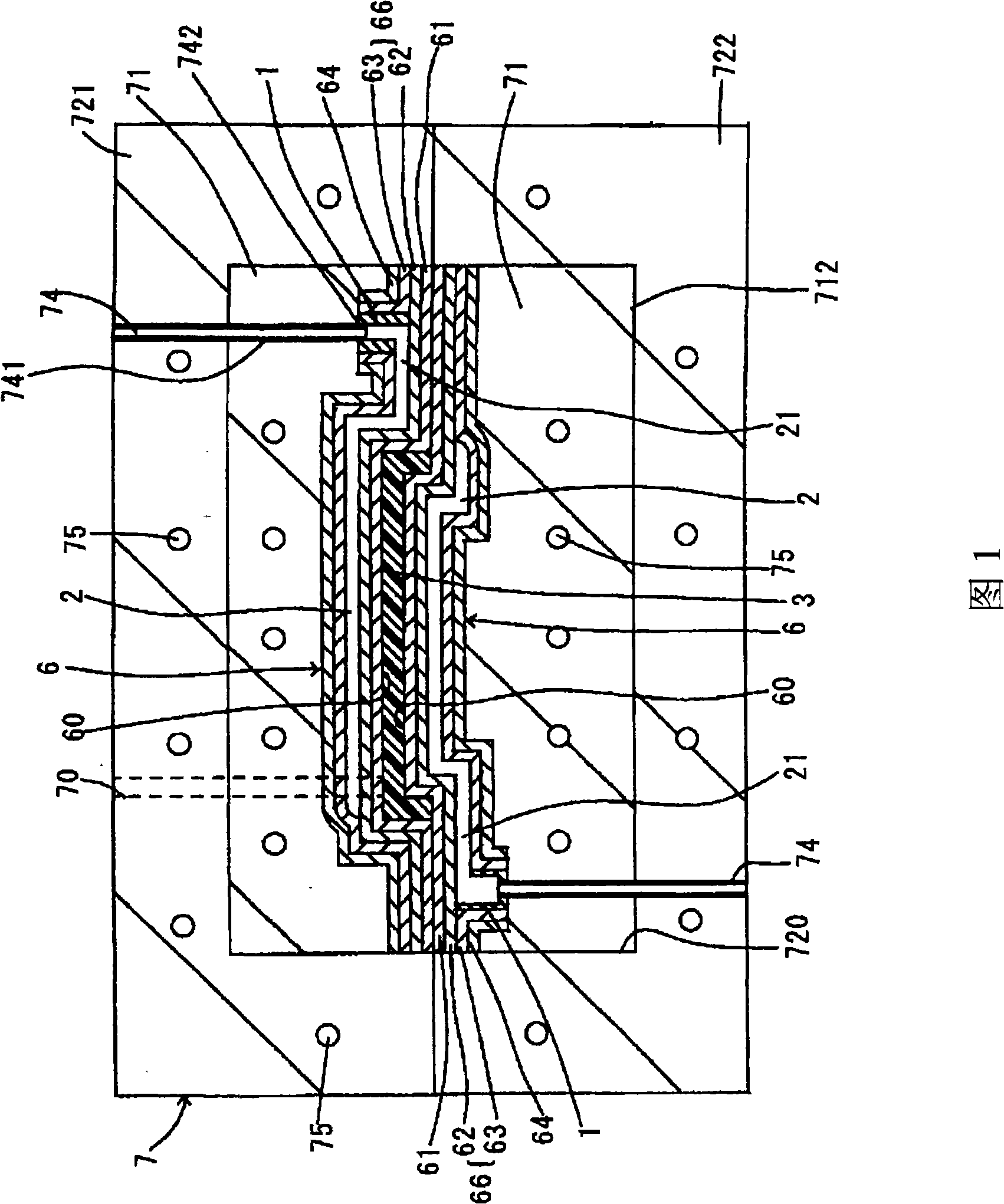
[0131] The electroforming casing formed in the electroforming mold according to the present invention has: a molding layer whose surface serves as a molding surface; a temperature regulating part in which a medium flow channel is formed between the first heat conducting layer and the second heat conducting layer and a reinforcing layer formed opposite to the shaping layer.

[0132] The shaping layer, the first thermally conductive layer, the second thermally conductive layer, and the reinforcing layer are all formed by an electroforming process. During electroforming, an electrolytic reaction is used to energize an electrolyte solution containing metal ions, and the target metal is deposited on the transfer surface of the master mold.

[0133] The first heat conducting layer and the second heat conducting layer are made of the same metal. The first and second thermally conductive layers may be made of high thermally conductive materials including copper and aluminum.

[0134...


PUM

PropertyMeasurementUnit
thicknessaaaaaaaaaa
thicknessaaaaaaaaaa
thicknessaaaaaaaaaa

Abstract

The invention discloses an electroformed mold, comprising an electroformed shell (6) having a forming surface (60) formed by electroform; a medium flowing passage (2) for cycling a heat medium so as to adjust temperature on the forming surface (60) formed in the electroformed shell (6); a back lining piece (71) adding lining for the electroformed shell (6); and a medium transport passage (74) respectively arranged on an upriver end (21) and a downriver end (22) for the heat medium flowing into or out of the medium flowing passage (2). A connection clamp (1) for connecting the medium flowing passage (2) and the medium transport passage (74) is embedded in the electroformed shell (6). The connection clamp (1) comprises a cavity formed inside, an opening hole, a section shape of which is basically identical to a radial section of the medium flowing passage (2) and a connection hole, a section shape of which is basically identical to an external radial section of a pipe piece of the medium transport passage (74). The opening hole is connected with the connection hole by the cavity.

Description

technical field [0001] The present invention relates to an electroforming mold suitable for use in injection molding and hollow molding and its manufacturing method. More particularly, the present invention relates to an electroforming forming die having a forming surface using electroforming technology and having heat medium flow passages for heating and cooling. Background technique [0002] The forming surface is formed by electroforming, and an electroforming forming mold is produced. The shape of the object surface can be transferred with high precision. Therefore, in recent years, electroforming molds have been used to mold resin products with precise surface shapes. [0003] Patent Document 1 discloses such an electroforming mold, forming such as Figure 27 shown. That is, on the front surface of the porous plate 91, the electroforming layer 931 as the molding surface 90 is formed. On the rear surface side of the porous plate 91, a pipe 92 for circulating a heat m...

Claims


Application Information

Patent Timeline
Patent Type & Authority Applications(China)
IPC IPC(8): C25D1/10
Inventor 饭村公浩古谷宗雄荒木昭次田中伸佳
Owner TOYODA GOSEI CO LTD
Why Eureka
Try Eureka