
Electrode device for spouting electric slurry as well as system thereof

An electrode device and electrode system technology, applied in the field of plasma jet electrode device and its system, can solve the problems of uneven treatment effect and low cost, achieve wide application range, improve industrial application surface, improve treatment area and uniformity sexual effect

Inactive Publication Date: 2008-10-01
郭月云
View PDF0 Cites 5 Cited by
  • Summary
  • Abstract
  • Description
  • Claims
  • Application Information

AI Technical Summary

Problems solved by technology

[0002] In recent years, using the principle of gas ionization (plasma), the removal of pollutants by gaseous oxidation has been researched and developed, such as electron beam method (Electron Beam), corona discharge method (Corona Discharge), microwave method (Microwave), high frequency electric Radio Frequency (RF), Dielectric Barrier Discharge (DBD), etc. have all been proven to have certain treatment effects. Among them, the dielectric discharge method can be effectively discharged under normal pressure. Discharge, and the cost is low, is one of the mainstream researches on the removal of pollutants by non-thermal plasma, and the dielectric plasma discharge method has been widely used in plastic film printing, ore electrostatic screening separator, ozone generation However, the non-thermal plasma is still in a high-temperature state, and there are still some deviations in the treatment of the surface of the workpiece and the treatment effect is not good. The disadvantages of uniformity still need to be further improved

Method used


Image

  • Electrode device for spouting electric slurry as well as system thereof
  • Electrode device for spouting electric slurry as well as system thereof
  • Electrode device for spouting electric slurry as well as system thereof

Examples


Embodiment Construction

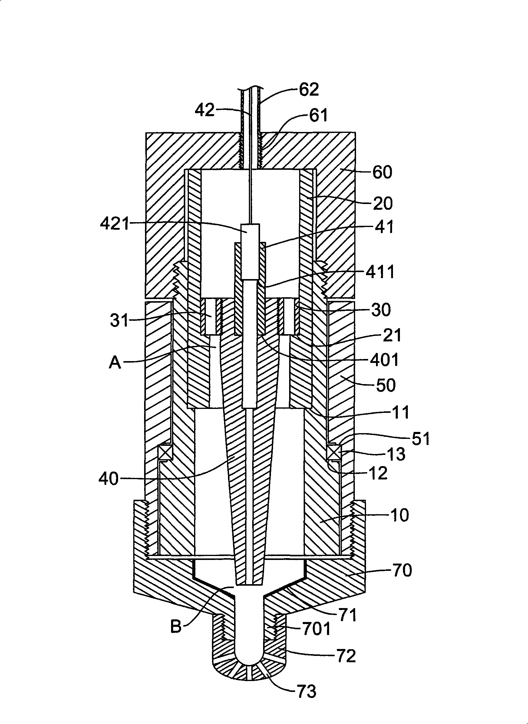
[0057] In order to further explain the technical means and effects of the present invention to achieve the intended purpose of the invention, the specific implementation and structure of the plasma jet electrode device and its system proposed according to the present invention will be described below in conjunction with the accompanying drawings and preferred embodiments. , features and their effects are described in detail below.

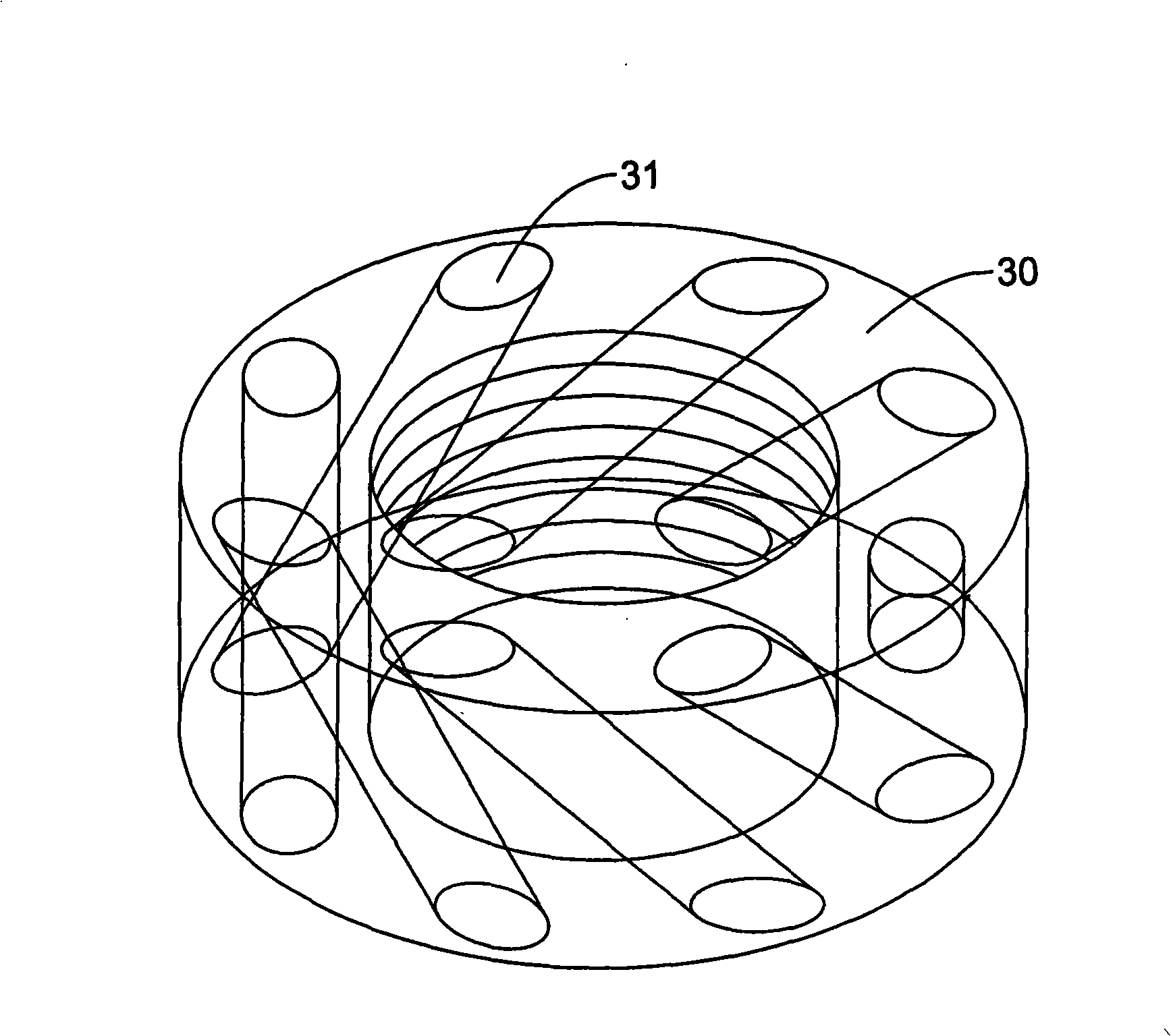
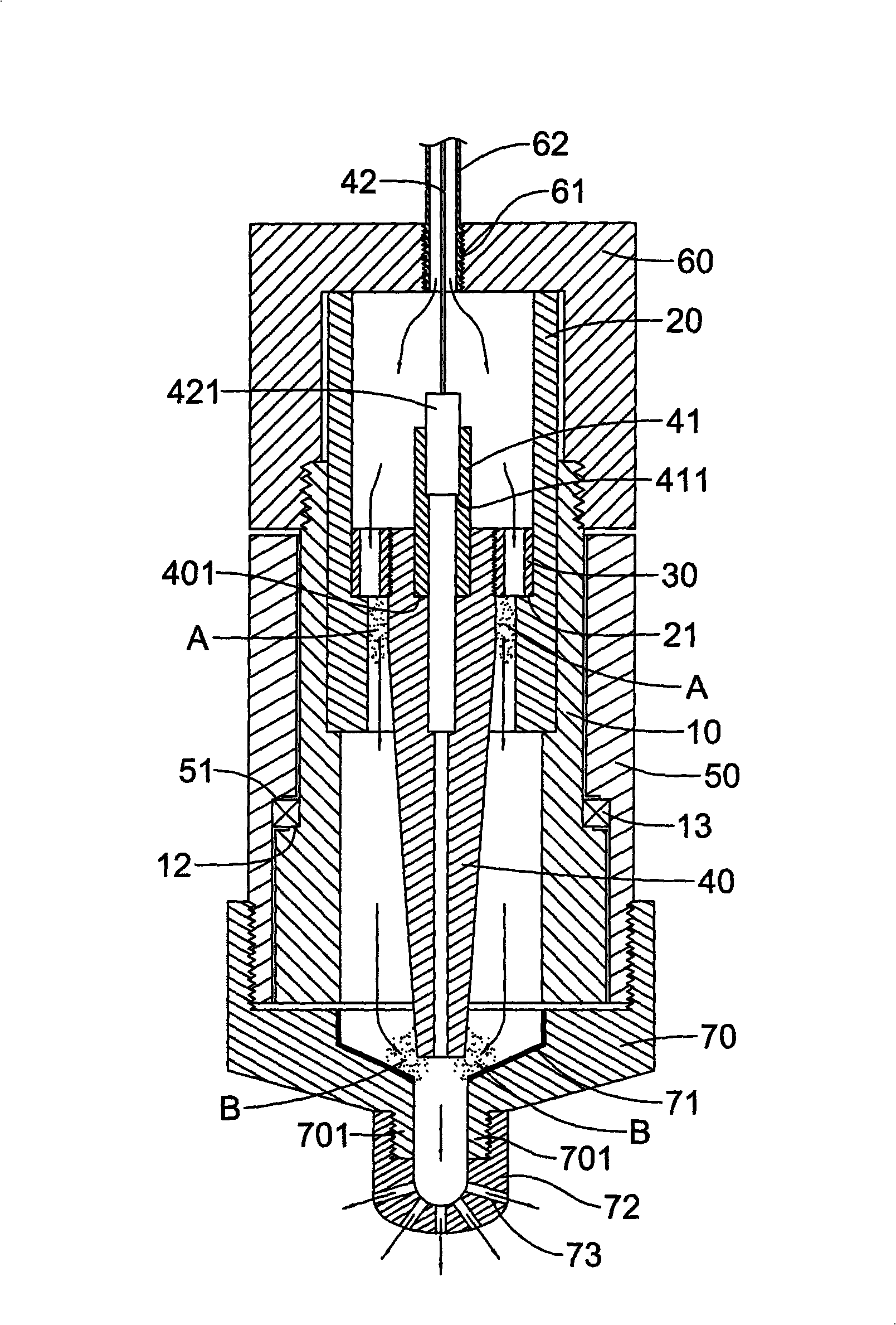
[0058] see figure 1 and figure 2 as shown, figure 1 It is a schematic cross-sectional view of the plasma jet electrode device of the present invention, figure 2 It is a three-dimensional schematic diagram of the disk in the plasma jet electrode device of the present invention. The plasma jet electrode device of the preferred embodiment of the present invention has a positioning seat 10, a ceramic tube 20 is arranged in the positioning seat 10, a disc 30 is arranged in the ceramic tube 20, and several The oblique hole 31 that runs through obli...


PUM


Abstract

The present invention provides an electric slurry jet electrode device and its system. The electric slurry jet electrode device comprises a locating base, a porcelain tube, a disk and a high voltage metal electrode, the disk is provided with a plurality of inclined holes which are slantways run through, a dielectric substance discharge slurry area is provided between the high voltage metal electrode and the porcelain tube, the device further comprises a rotary base, a chassis and a grounding electrode, a low temperature non-balanced slurry area is formed between the grounding electrode and the high voltage metal electrode, a nozzle head having a magnetic around it is mounted on the bottom of the chassis; thus, the design ensures the stronger slurry generate and flowingly forms a turbulent mode, rotatablely ejecting by the nozzle head, thereby improving the processing area and evenness of the electric slurry. The electric slurry jet electrode system fixes at least one electric slurry jet electrode by a supporter, greatly enhancing the processing area of the electric slurry, and improving the functions of cooling, introduction, film coating and etching and the like of the parts.

Description

technical field [0001] The invention relates to a plasma jet electrode device, in particular to an unbalanced plasma jet that can be produced at low temperature and normal pressure, and can improve the plasma treatment area and uniformity, so as to achieve a more ideal Plasma jet electrode device and its system for workpiece surface treatment effect. Background technique [0002] In recent years, using the principle of gas ionization (plasma), the removal of pollutants by gaseous oxidation has been researched and developed, such as electron beam method (Electron Beam), corona discharge method (Corona Discharge), microwave method (Microwave), high frequency electric Radio Frequency (RF), Dielectric Barrier Discharge (DBD), etc. have all been proven to have certain treatment effects. Among them, the dielectric discharge method can be effectively discharged under normal pressure. Discharge, and the cost is low, is one of the mainstream researches on the removal of pollutants b...

Claims


Application Information

Patent Timeline
Patent Type & Authority Applications(China)
IPC IPC(8): H05H1/34
Inventor 郭月云
Owner 郭月云
Learn More