Oil-gas separating device of general-purpose petrol engine crankshaft case waste gases

A separation device and general-purpose gasoline technology, applied to engine components, crankcase ventilation, machines/engines, etc., can solve problems such as shortened life, reduced engine performance, and excessive engine emissions, so as to reduce carbon deposits, ensure performance and use The effect of longevity

Inactive Publication Date: 2008-10-08
LONCIN MOTOR
View PDF0 Cites 4 Cited by
  • Summary
  • Abstract
  • Description
  • Claims
  • Application Information

AI Technical Summary

Problems solved by technology

However, since the filling for filtering exhaust gas is usually made of wire mesh or foam material, it is conducive to the attachment of oil droplets. The lower part of the separation chamber will be driven into the air filter by the strong positive pres

Method used


Image

  • Oil-gas separating device of general-purpose petrol engine crankshaft case waste gases
  • Oil-gas separating device of general-purpose petrol engine crankshaft case waste gases

Examples


Embodiment Construction

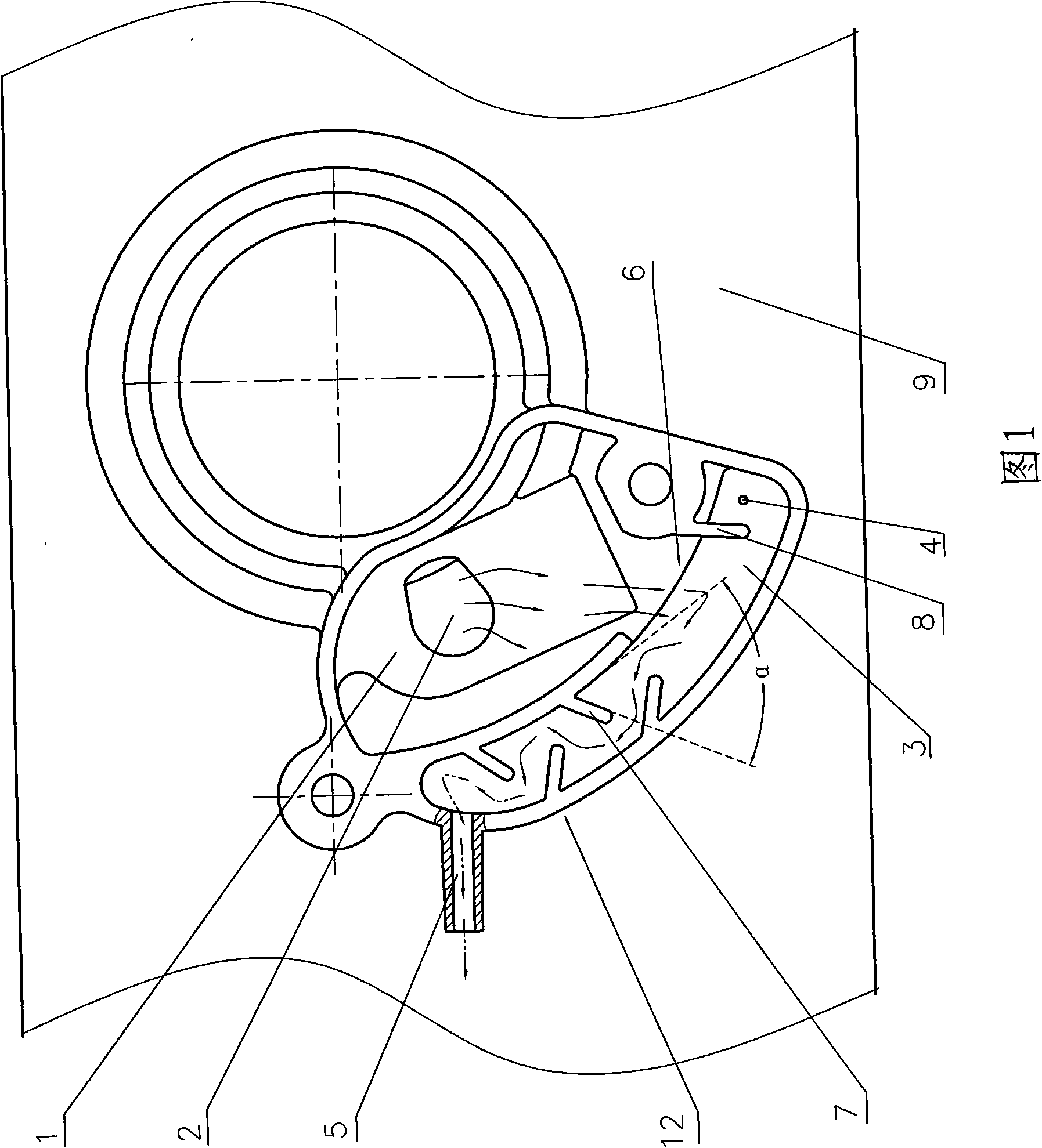
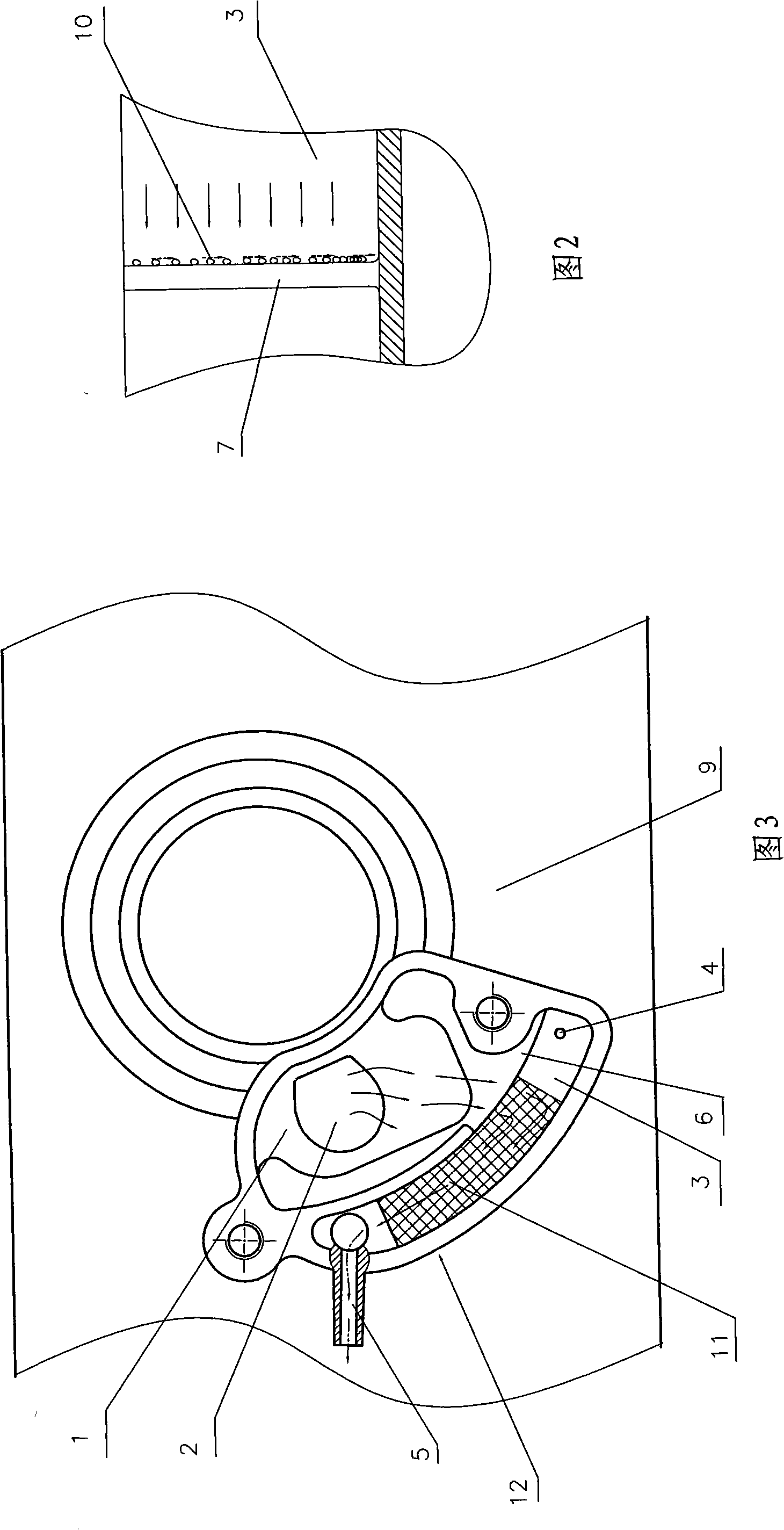
[0013] 1 and 2, the oil-gas separation device 12 is arranged on the crankcase 9, and the oil-gas separation device 12 can be integrally cast with the crankcase 9, or can be made separately and fixed on the crankcase body with screws. The oil-gas separation device 12 has an intake buffer chamber 1 and an oil-gas separation chamber 3, the air inlet 2 of the oil-gas separation device 12 communicates with the inside of the crankcase 9, the upstream inlet 6 of the oil-gas separation chamber 3 communicates with the intake buffer chamber 1, and the oil and gas The air outlet nozzle 5 of the separation device 12 is located at the downstream of the oil-gas separation chamber, and the air outlet nozzle 5 is connected with the air filter (not shown) through a breather pipe, and the bottom of the oil-air separation chamber 12 is provided with an oil return valve communicated with the crankcase 9. Hole 4, the upstream inlet 6 of the oil-gas separation chamber is located between the oil retu...


PUM


Abstract

The invention discloses an oil gas separation device for crankcase waste gas of a general gasoline engine, which comprises an intake buffering cavity and an oil gas separation cavity; the gas inlet of the oil gas separation device is in communication with the inside of the crankcase; the upstream inlet of the oil gas separation cavity is positioned between an oil return hole and an outgassing mouth and is communicated with the intake buffering cavity; the outgassing mouth of the oil gas separation device is arranged at the lower steam of the oil gas separation cavity; the lower part of the oil gas separation cavity is provided with the oil return hole communicated with the inside of the crankcase; walls at the two sides of the oil gas separation cavity are respectively provided with a plurality of structures which stretch from the wall at the side to the opposite slanchwise to prevent gas flow from passing directly; the structures on the walls at the two sides used to prevent gas flow from passing directly are in staggered arrangement at intervals and the extension length of each structure used to prevent gas flow from passing directly is less than the width of the oil gas separation cavity and more than one second of the width of the oil gas separation cavity, and the extension end declines to the upstream direction. The device does not adopt fillers and can effectively separate the oil and gas from the waste gas and avoid oil droplets from being taken into the combustion chamber.

Description

technical field [0001] The invention relates to the field of exhaust gas discharge from engine crankcases, in particular to an oil-gas separation device for crankcase exhaust gas of general gasoline engines. Background technique [0002] With the need for environmental protection, the requirements for exhaust emissions of general-purpose gasoline engines are getting higher and higher. Generally, existing general-purpose gasoline engines are usually provided with an oil-gas separation device on the crankcase body of the engine, and its function is to reduce thermal expansion in the crankcase The exhaust gas is discharged to balance the pressure in the crankcase; at the same time, the oil mixed in the exhaust gas is separated, so that the separated oil flows back into the crankcase for lubrication, and the exhaust gas separated from the oil is sent to the air filter Clean the device and re-enter the combustion chamber to participate in the combustion. Therefore, the exhaust g...

Claims


Application Information

Patent Timeline
IPC IPC(8): F01M13/04
Inventor 景华阳骆勇车碧波陈明松
Owner LONCIN MOTOR
Why Eureka
Try Eureka